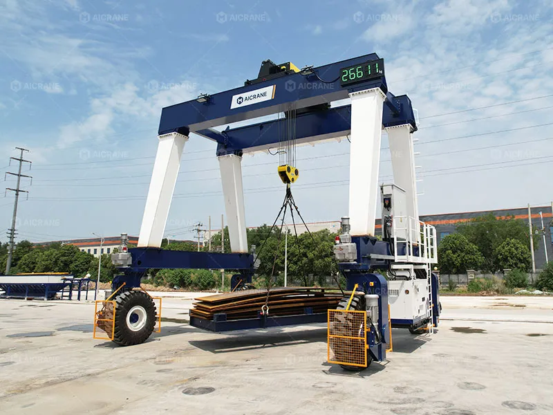
- Rail-Free Operation → Lower Infrastructure Cost
- Rubber-Tyred Mobility → Wider Working Range
- Double-Girder A-Frame → Stable Heavy-Load Handling

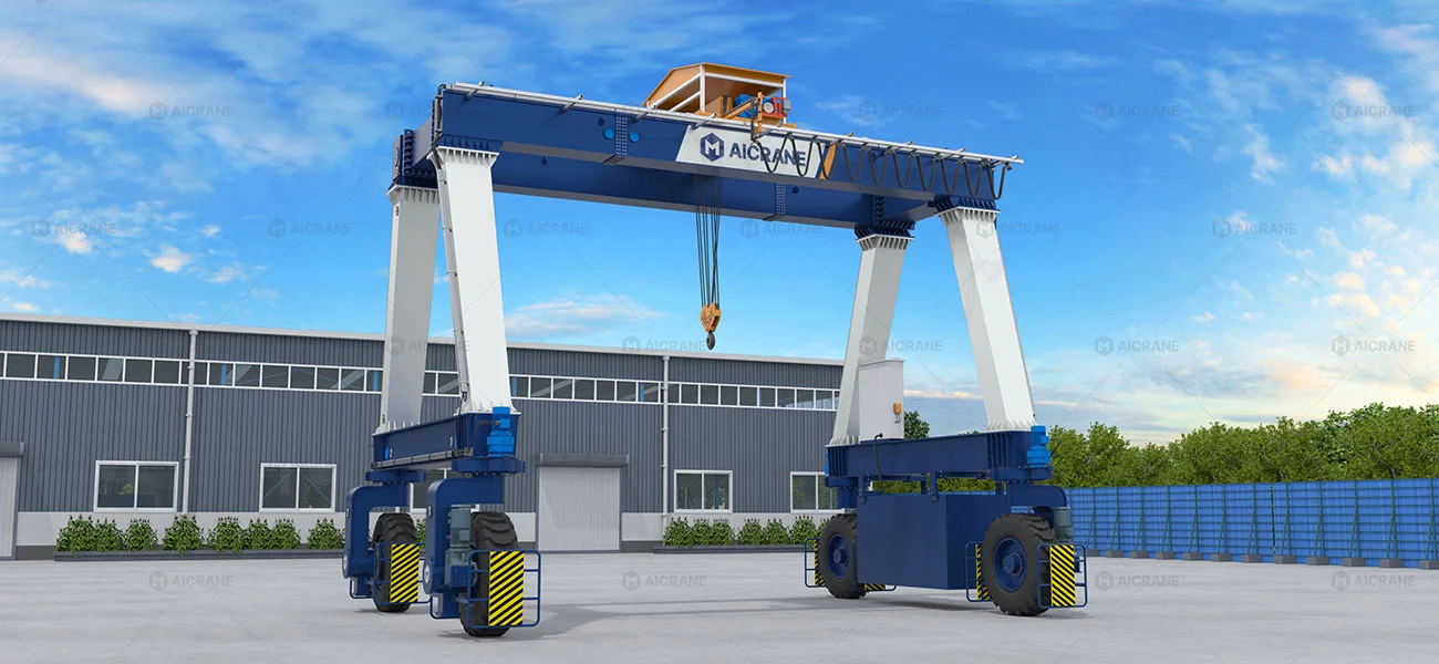
The MGT double girder rubber tyred gantry crane is an A-frame mobile gantry crane designed to lift and transfer heavy industrial cargo in factories, workshops, and yards. Typical loads include steel plates, steel coils, structural steel components, machinery parts, automotive molds, tanks, and precast elements requiring repeated lifting, transfer, storage, or truck loading and unloading.
Its double-girder A-frame structure provides the rigidity required for demanding heavy-load handling, while rubber-tyred travel allows the crane to move between multiple working positions without fixed rails. MGT is particularly suited to conventionally dimensioned heavy cargo where one lifting system needs to serve production, storage, assembly, and loading areas.
MGT Double Girder RTG Crane Technical Specifications
MGT rubber tyred gantry crane is available in different configurations based on lifting capacity, span, lifting height, working class, travel requirements, and cargo dimensions. Its standard specification range is:
| Parameter | MGT Specification |
|---|---|
| Crane Type | Double Girder Rubber Tyred Gantry Crane |
| Leg Structure | A-Type |
| Lifting Capacity | 5-100 t |
| Span | 5-20 m |
| Lifting Height | 5-15 m |
| Working Class | A3-A6 |
| Power Supply | Diesel generator / Cable reel / Battery |
| Control Mode | Pendant / Wireless Remote Control/Cabin |
| Steering Modes | Straight / 90° Transverse / Crab / Pivot |
Key Parameters for MGT Crane Selection
- Lifting capacity should be based on the heaviest regular load to be handled, with appropriate allowance for the required operating conditions.
- Span should match the width of the working area and the required clearance around the cargo.
- Lifting height depends on cargo height, stacking requirements, truck loading height, and available overhead clearance.
- Working class should match the frequency and intensity of crane operation, including lifting cycles and expected workload.
- Cargo dimensions should be considered together with capacity, as load length, width, and height can affect the required crane clearance and overall configuration.
MGT Crane Projects: Solving Complex Customer Challenges
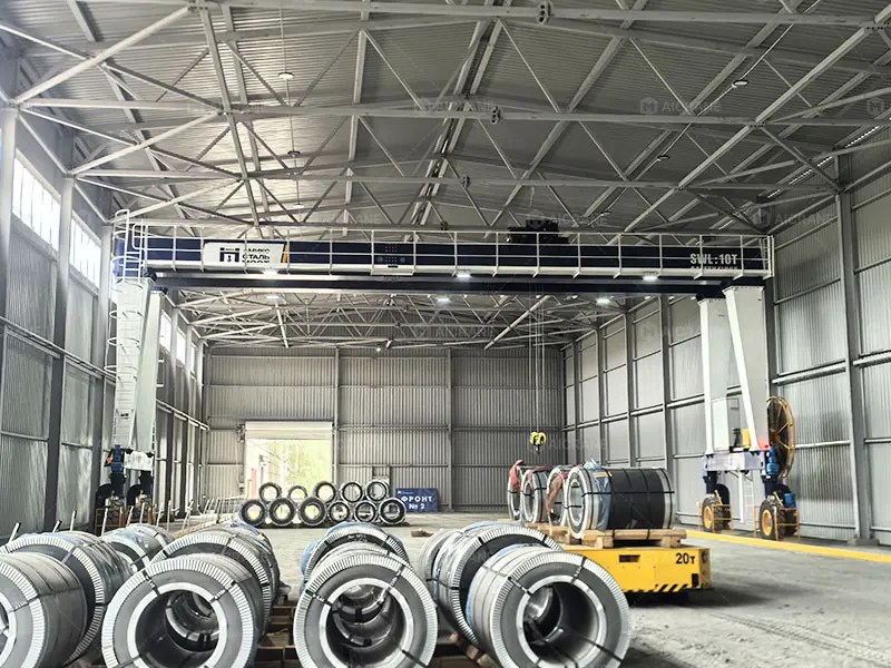
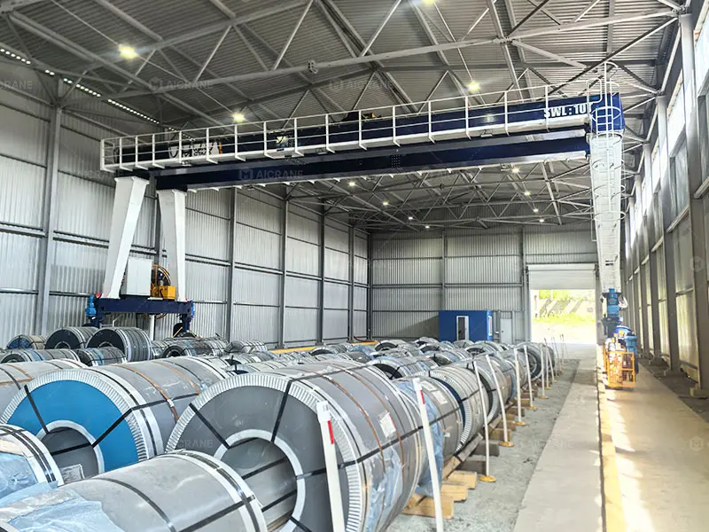
MGT 10 Ton: Saving 30%+ in Civil Building Costs for a Russian Steel Company
Customer Challenges
- High civil costs: A traditional bridge crane required expensive concrete runway beams and supporting column brackets.
- Limited workshop width: The crane needed a large working span while travelling close to the building walls.
- Cold-weather operation: The customer required a continuous power supply reliable in freezing sub-zero conditions.
- High stability demand: Heavy, repeated steel coil handling required high structural rigidity.
MGT Engineering Solutions
- Ground-running design: Eliminates overhead runway beams, operating directly on the prepared concrete floor.
- Customized A-frame geometry: Engineered with a tailored span and tight wall-side clearance to maximize workshop bay coverage.
- Cable reel power supply: Delivers steady electric power without relying on onboard batteries in sub-zero conditions.
- Double girder structure: Provides high structural rigidity and durability for heavy, repeated coil lifting.
Operational Results
- 30%+ estimated savings in crane-related civil and structural support costs.
- Maximized workshop coverage with an optimized clear span and close wall-side operation.
- Reliable electric power throughout sub-zero winter handling conditions.
- Stable handling performance for continuous steel coil and plate transfer.
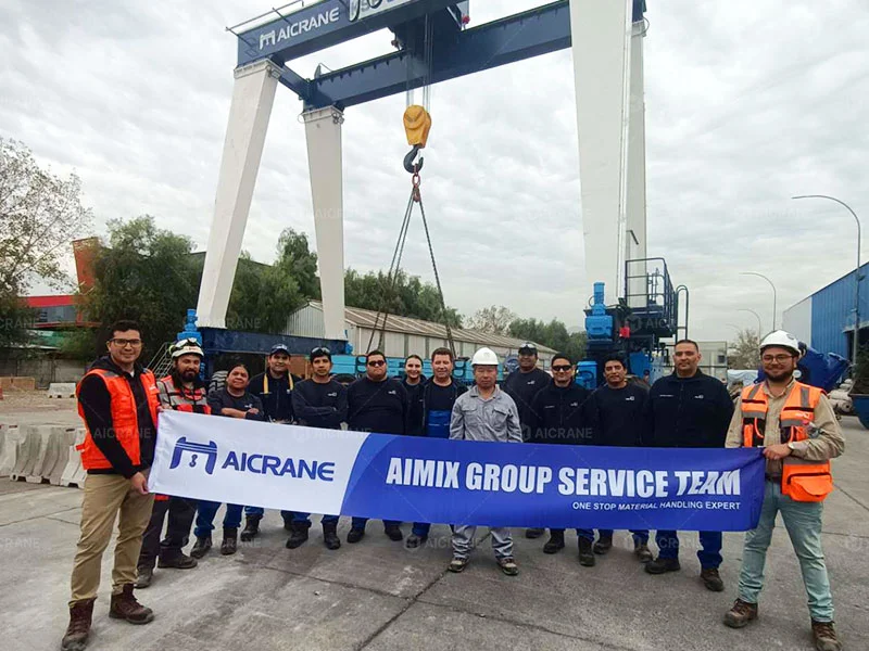
MGT 50 Ton: Cutting Crane Rental Costs and Expanding Working Range for a Chilean Pump & Valve Company

Customer Challenges
- High rental expenses: Relying on third-party truck-mounted cranes for regular loading and unloading increased operating costs.
- Restricted handling range: Truck-mounted cranes required specific positioning, limiting flexibility across the yard.
- Safety and stability: Handling high-value pumps and valves required smooth and controlled lifting and positioning.
- Multiple work zones: The customer needed to serve assembly, storage, and dispatch areas without fixed crane locations.
MGT Engineering Solutions
- 50 t handling capacity: Custom-engineered for heavy pump and valve handling, with a 10.7 m span and 10 m lifting height.
- Rail-free multi-zone mobility: Rubber-tyred travel allows the crane to move between different yard areas without fixed rails.
- Smooth lifting and lowering: Variable-speed control supports controlled positioning during truck loading and unloading.
- Wide working coverage: The crane covers storage areas and truck loading zones with a single mobile lifting system.
Operational Results
- Reduced rental dependence: The customer gained a dedicated in-house solution for routine heavy-load handling.
- Expanded working range: One MGT serves multiple assembly, storage, and dispatch areas.
- Improved handling safety: Controlled lifting and positioning reduce the risk of load impact during handling.
- More efficient truck handling: The crane supports faster and more consistent loading and unloading operations.
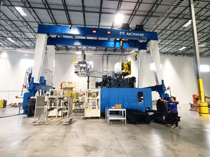
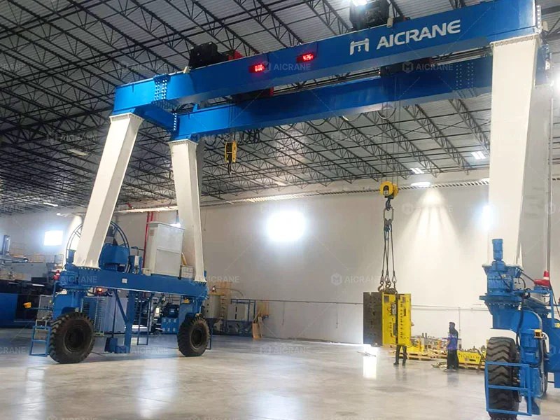
MGT 32/20 Ton: Heavy Mold Handling Without Structural Modification in a Rented U.S. Warehouse
Customer Challenges
- Rented warehouse: The customer leased the facility and did not want to modify the existing building structure or install overhead crane runway beams.
- Heavy mold handling: Automotive injection molds required lifting and handling inside the warehouse, with peak loads of up to 32 t.
- Mold turning: The molds required controlled 180° flipping, requiring two hooks to work together during repositioning.
- Limited headroom: The existing warehouse had restricted clearance, requiring the crane to fit the available building space while maintaining the required lifting height.
MGT Engineering Solutions
- Ground-running design: The rubber-tyred gantry operates on the warehouse floor without modifying the existing building structure.
- 32/20 t capacity: The crane is designed for peak loads up to 32 t, while typical daily mold handling is around 20 t.
- Dual-trolley system: Two independently controlled hoist trolleys allow the hooks to work together for controlled mold flipping.
- Compact configuration: The MGT was engineered with a 9.5 m overall height and 7.7 m lifting height to meet the warehouse’s clearance and handling requirements.
Operational Results
- No structural modification: The customer added indoor heavy-lifting capability without altering the leased warehouse.
- Controlled mold flipping: Dual-hook operation provides stable and coordinated 180° mold turning.
- Required lifting height: The compact MGT configuration provided the necessary lifting height within the existing warehouse.
- Flexible daily handling: The MGT supports routine 20 t mold handling and peak 32 t operations within the existing warehouse.
How MGT Is Configured Around Different Handling Requirements
The three projects above had different requirements: avoiding runway-beam construction, expanding handling coverage across multiple work areas, and turning heavy automotive molds. MGT accommodates these differences through specific hoisting, power, mobility, structural, and lifting configurations.
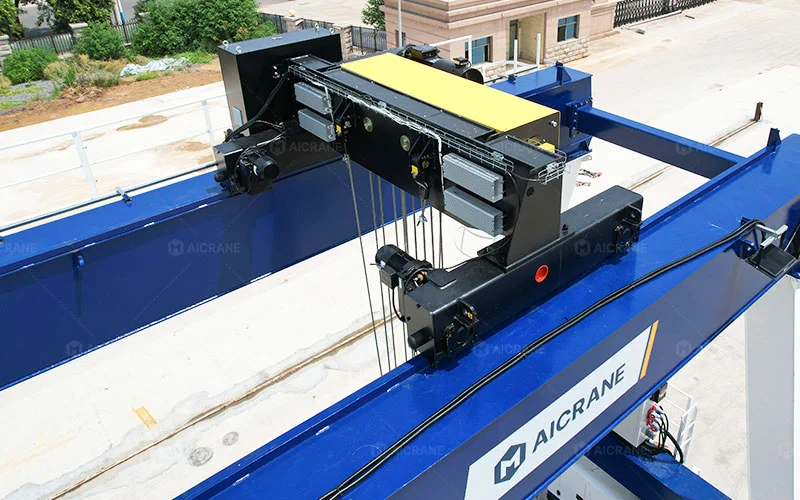
Hoisting & Trolley Configurations
- Electric Hoist Trolley: A compact, cost-effective option for smaller-capacity loads and routine industrial lifting.
- Winch Trolley: A robust option for higher-capacity and heavy-duty lifting where a stronger hoisting arrangement is required.
- Dual-Trolley System: Two independently controlled trolleys work together for long loads or controlled mold and die flipping.
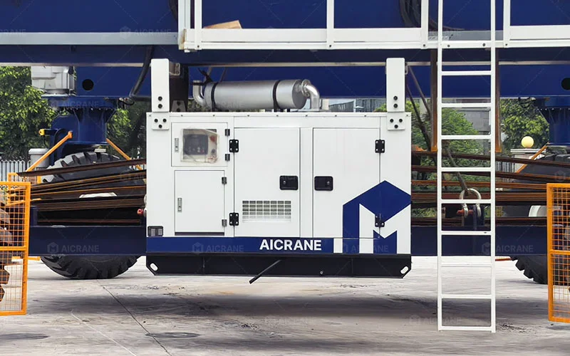
Power Supply for Different Yard Conditions
- Motorized Cable Reel: Suitable for stable power supply and fixed, well-organized working areas, especially where cable infrastructure already exists or is planned.
- Onboard Diesel Generator: Suitable for large yards with incomplete power infrastructure and frequent crane relocation.
- Battery Power: Suitable for low-emission applications where cable-free operation is preferred.
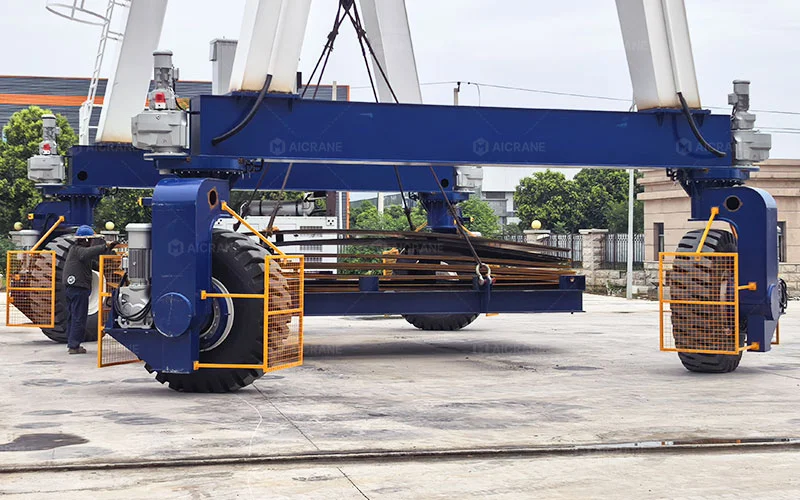
Mobility for Flexible Yard Handling
MGT supports multiple steering modes for maneuvering and positioning across industrial working areas:
- Straight Travel: Forward and reverse movement along the main travel direction.
- 90° Crab Steering: Sideways movement for cross-bay travel and positioning.
- 45° Diagonal Steering: Diagonal movement for repositioning within open working areas.
- Pivot Steering: Pivoting movement for tighter maneuvering and positioning.
- Ackermann Steering: Controlled, vehicle-like steering for maneuvering along different travel paths.
Structural & Dimension Configuration
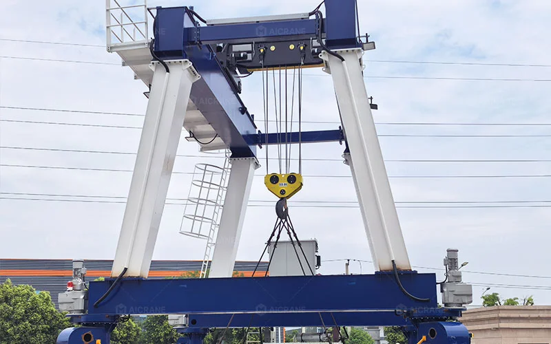
- A-Type Leg Structure: The standard MGT gantry arrangement for heavy industrial handling.
- Span: Matched to the required working width and cargo handling area.
- Lifting Height: Matched to cargo height, stacking requirements, and the handling process.
- Overall Height & Wall Clearance: Adapted to existing workshop structures and available operating space.
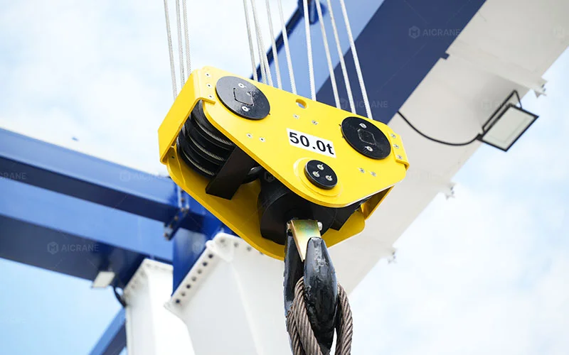
Below-the-Hook Equipment
- C-Hook & Coil Lifter: For dedicated steel coil handling and transfer.
- Lifting Beam & Frame: For multi-point lifting of long beams, pipes, and irregularly shaped components.
- Specialized Attachments: Configured according to cargo geometry, lifting points, and specific handling requirements.
Why A-Frame Structural Geometry for MGT Rubber Tyred Gantry Crane?
The A-frame leg structure is the standard support geometry of MGT gantry crane, providing a rigid and stable connection between the double girder structure and the rubber-tyred travel system.
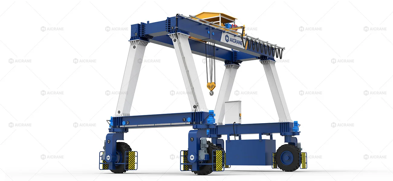
Stable Load TransferThe inclined legs provide a direct structural load path from the girders to the wheel assemblies, supporting stable lifting and travelling under heavy loads.
Structural RigidityThe A-frame geometry increases the rigidity of the gantry structure, helping control deformation and movement during lifting, travelling, and braking.
Balanced Gantry SupportThe angled leg arrangement provides a stable support base for the crane structure while maintaining the open working space required for industrial cargo handling.
MGT vs DTLS: Which Configuration Fits Your Cargo?
Both MGT and DTLS are double girder rubber tyred gantry cranes, but their leg configurations support different cargo-handling requirements. MGT is generally suited to conventionally dimensioned heavy industrial cargo, while DTLS is more suitable when cargo length, overall dimensions, internal clearance, or multi-point lifting become the main design considerations.

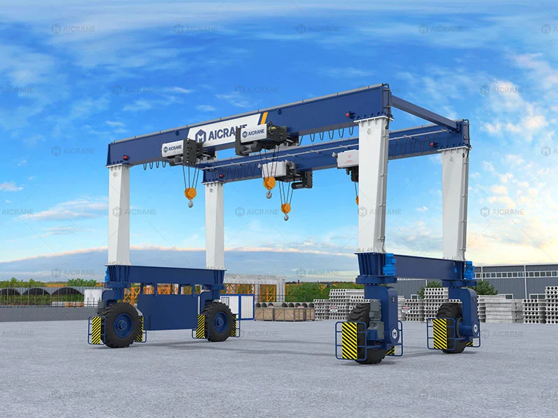
| Factor | MGT | DTLS |
|---|---|---|
| Leg Structure | A-Type | U-Type |
| Girder | Double Girder | Double Girder |
| Cargo Profile | Regular / conventionally dimensioned heavy cargo | Long, oversized, or dimensionally extended cargo |
| Handling Focus | General heavy-load lifting and transfer | Long-load and clearance-sensitive handling |
| Lifting Configuration | Standard lifting arrangement | Two-point or four-point lifting for long or demanding loads |
| Typical Applications | Steel products, machinery components, molds, tanks, precast elements | Long structural components, containers, long steel products, and other dimensionally extended loads |
| Key Selection Factor | Conventional cargo envelope and required working clearance | Cargo dimensions, lifting-point arrangement, and required internal clearance |
Which Configuration Fits the Cargo?
- Choose MGT crane when the load generally falls within a conventional cargo envelope and does not require an extended internal clearance or multi-point lifting arrangement.
- Consider DTLS rubber tyred gantry crane when cargo length or overall dimensions become a primary design constraint, particularly when the load requires greater internal clearance or two-point or four-point lifting.
The selection should be based on cargo dimensions, lifting-point arrangement, required clearance, and the actual handling process -not lifting capacity alone.
What Should Be Checked Before MGT Crane Selection?
MGT selection depends on far more than cargo weight alone. Cargo dimensions, required clearance, lifting-point arrangement, center of gravity, handling path, and operating conditions all affect the suitable crane configuration.
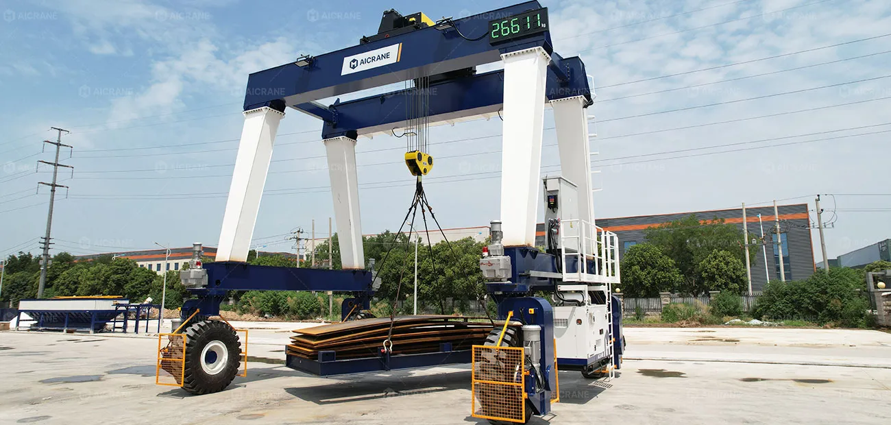
Cargo DimensionsLength, width, and height define the required working envelope, gantry span, lifting height, and net internal clearance within the A-frame structure.
Lifting-Point ArrangementThe number and location of lifting points determine whether a single-hook, dual-trolley system, or specialized equalizer beam is required for stable handling.
Required ClearanceThe necessary safety margins between the cargo and MGT legs, main girders, storage stacks, trailers, and facility obstacles during lifting and travel.
Center of Gravity (CoG)Identifying an offset CoG is critical for asymmetric or irregular loads, helping determine lifting accessories and load-balancing arrangements to keep the suspended cargo stable.
Handling PathThe complete operational cycle – including lifting, traveling, repositioning, rotating, and setting down the cargo within the designated yard or workshop area.
Working ConditionsLifting frequency, duty cycle, travel distance, and operating environment affect the required MGT structural duty rating (ISO/FEM) and subsystem configuration.
What Ground Conditions Are Required for an MGT Rubber Tyre Gantry Crane?
An MGT rubber tyred gantry crane does not require permanent rails or overhead runway beams, but the ground must support its concentrated wheel loads and allow stable travel under load.
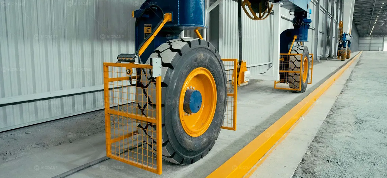
Ground TypeMGT crane can operate on reinforced concrete, cement, asphalt, or well-compacted soil. Interlocking paver surfaces require technical verification based on site photos and ground conditions.
Ground Bearing CapacityThe ground must withstand the MGT’s maximum wheel and axle loads during lifting, traveling, acceleration, and braking. Required capacity depends on crane capacity, self-weight, wheel configuration, and operating conditions.
Maximum SlopeThe standard MGT crane configuration can travel fully loaded on slopes up to 4°, subject to the specific crane design and operating conditions. For sloped sites, provide the maximum slope angle and the length of the sloped section in meters for engineering review.
Surface ConditionThe travel route should be free from deep potholes, soft or uncompacted areas, sharp level changes, and obstacles that could affect tyre contact, traction, or crane stability.
Engineering Site Evaluation: Aicrane can calculate the MGT’s maximum wheel loads based on the crane capacity, dead weight, span, wheel configuration, and operating conditions, allowing the civil team to verify the existing ground or pavement before delivery.
MGT Crane FAQs
What is an MGT crane used for?
What factors determine the right MGT configuration?
How much can an MGT rubber tyred gantry crane lift?
How does an MGT crane move around a yard?
How is an MGT crane powered?
How much does an MGT rubber tyred gantry crane cost?
What information is needed to quote an MGT rubber tyred gantry crane?
Designed Around Your Cargo. Configured for Your Site.
The right MGT double girder rubber tyred gantry crane configuration starts with your actual cargo, handling process, and site conditions. From lifting capacity and cargo dimensions to travel path, ground conditions, and working clearance, each design detail should support safe and efficient heavy-load handling.
Ready to evaluate an MGT crane for your facility?
Share your load capacity, cargo dimensions, span, lifting height, and travel requirements with our team to discuss the right MGT configuration for your application.