

The safety of precast concrete during handling is determined not only by weight, but more importantly by the beam’s geometry and cross-sectional behavior under lifting loads. In practice, the success of a lift depends on how well the lifting system matches the structural profile of the element – from de-molding to transport and final installation. This guide explains how different spreader configurations are selected based on precast shape and structural requirements to ensure safe and controlled handling throughout the entire lifting process.
Classification of Precast Concrete Beams and Their Handling Characteristics
In precast concrete operations, beam geometry is the primary factor that determines lifting behavior. Each cross-section responds differently to load transfer, which means rigging methods must be adapted to avoid structural damage during handling.
T-Beams and Double-T Slabs
These are widely used in parking structures and bridge decks, with wide flanges and relatively thin sections.
- Handling characteristics: High surface area with slender cantilevered edges.
- Main risk: Edge spalling caused by any non-vertical lifting angle. Even small horizontal force components can damage unreinforced flange zones.
- Key requirement: Strict vertical load alignment to protect flange integrity during lifting.
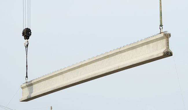
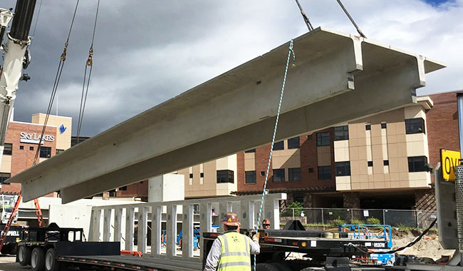
I-Girders
Common in highway bridge construction, designed for efficient span and vertical load resistance.
- Handling characteristics: Tall, narrow profile with a relatively high center of gravity.
- Main risk: Lateral instability during lifting or transport. Without proper control, the girder can tilt or develop lateral-torsional deformation.
- Key requirement: Elimination of side forces and controlled vertical lifting to maintain stability.
U-Beams (Channel Girders)
Used in viaducts and transit structures, typically open-topped before in-situ deck casting.
- Handling characteristics: Open section with incomplete torsional stiffness.
- Main risk: Twisting or web deformation during lifting due to lack of closed structural form.
- Key requirement: Synchronized lifting to maintain geometry and prevent section distortion.
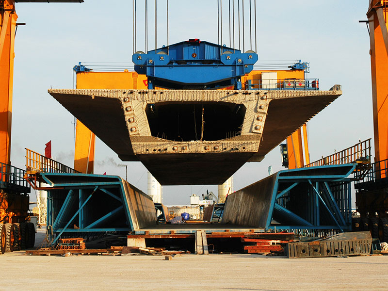
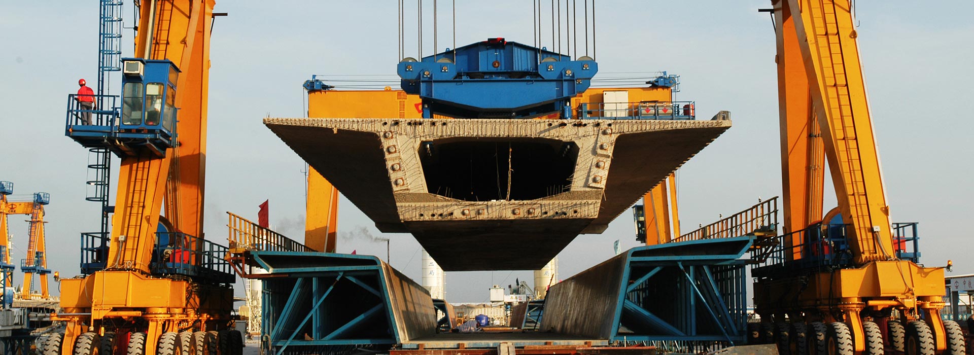
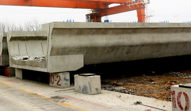
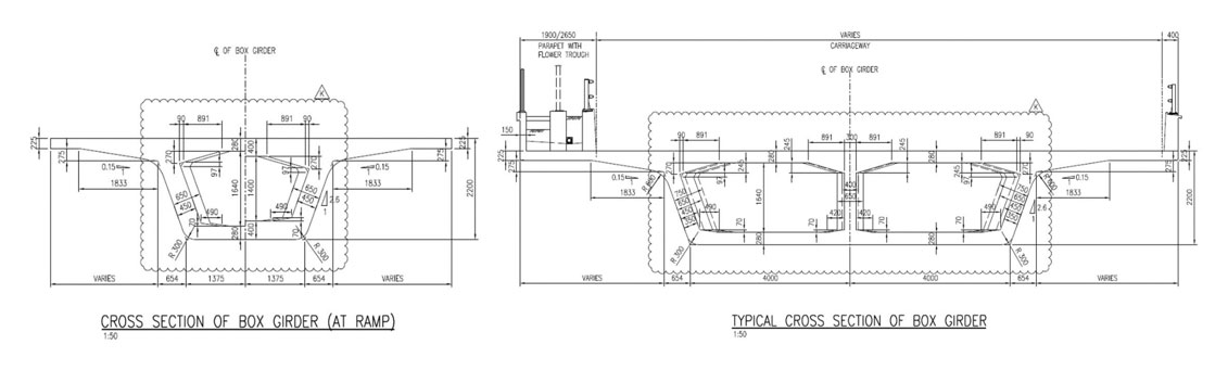
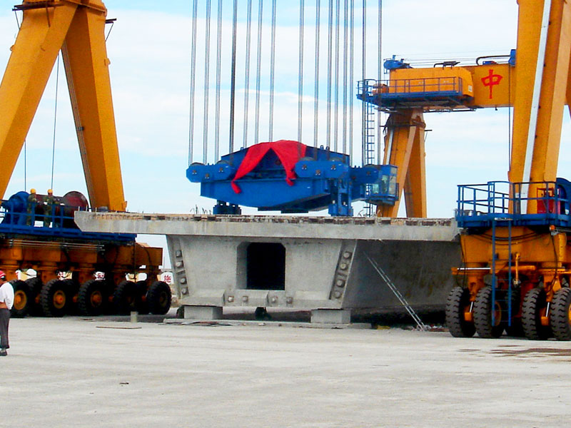
Box Girders
High-capacity enclosed sections used in long-span and heavy-duty infrastructure.
- Handling characteristics: Fully closed, high rigidity, often extremely heavy (100t+).
- Main risk: High localized stress at lifting points due to mass concentration.
- Key requirement: Accurate load distribution through designed lifting points to avoid concrete overstress or anchor failure.
These geometry differences directly determine how lifting forces are applied during handling, requiring tailored load distribution and rigging design approaches.
How Beam Geometry Drives Rigging Strategy Selection
In precast lifting operations, rigging design is never a one-size-fits-all solution. The geometry of the girder directly determines how loads are distributed, how lifting points should be arranged, and whether a simple sling system is sufficient or a more advanced spreader beam configuration is required.
Load Distribution Starts with Beam Length
Longer girders introduce greater sensitivity to bending and deflection during lifting. As the span increases, the distance between lifting points becomes a critical design factor.
- Short girders may be lifted with two-point rigging systems.
- Longer girders typically require multi-point lifting or spreader beam systems to reduce mid-span bending moments.
- Excessive spacing between lifting points can lead to localized stress concentration and surface cracking.
As a result, rigging layout must scale proportionally with beam length to maintain structural stability during hoisting.
Cross-Section Type Determines Rigging Symmetry
The shape of the precast girder significantly influences how loads are transferred into the lifting system.
- I-shaped and T-shaped girders often require carefully balanced lifting points to avoid uneven stress distribution.
- Box girders generally provide more uniform stiffness, allowing more flexible rigging layouts.
- Solid rectangular sections tend to distribute loads more evenly but require higher overall lifting capacity.
This means that cross-section geometry directly affects whether symmetric or adaptive rigging arrangements are required.
Width and Edge Distance Affect Sling Positioning
Beam width plays an important role in determining safe sling placement. However, the lifting arrangement is not always designed to match the full physical width of the beam. Instead, you should focus on:
- Edge strength zones
- Reinforcement layout
- Allowable stress areas around lifting inserts
For wider sections, rigging systems often require outward extension of lifting points or adjustable spreader arms to maintain optimal sling angles and avoid excessive lateral compression.
Height Influences Stability and Rotation Control
Beam depth affects the elevation of the center of gravity, which directly impacts rotational stability during lifting. Tall or deep sections are more prone to:
- Tilting during hoisting
- Rotational instability
- Uneven load sharing between lifting points
To address this, rigging systems may incorporate:
- Anti-rotation slings
- Equalizer beams
- Multi-level lifting point configurations
Center of Gravity Offsets Require Adjustable Rigging
Not all precast girders have a symmetrical mass distribution. Embedded ducts, reinforcement variations, and lifting insert positioning can shift the center of gravity away from the geometric center. When this occurs, rigid lifting systems may lead to uneven loading.
To compensate, engineers may use:
- Adjustable sling lengths
- Equalizing beams
- Load monitoring systems for real-time balance correction
This ensures that the lifting force remains aligned with the true center of gravity rather than the geometric midpoint.
Lifting Insert Layout Defines the Final Rigging Architecture
Even with an optimized spreader design, the final rigging configuration is constrained by the position and spacing of embedded lifting inserts.
If inserts are:
- Too close together → increased sling angle and higher tension forces
- Too far apart → may require extended spreader beams
- Asymmetrically placed → requires load equalization systems
Therefore, spreader beam design must always be coordinated with the casting-stage insert layout.
Precast Concrete Handling: Choosing the Right Rigging Setup
Precast girder handling uses different lifting setups depending on beam geometry, weight distribution, and lifting point layout. These systems connect the crane hook to the concrete element and ensure controlled, stable lifting. Below are the main types of lifting equipment commonly used in precast operations.
Wire Rope Slings (Direct Rigging)
The simplest setup – but also the most risky.
Wire rope slings connect directly to lifting anchors using shackles. The problem is the sling angle. As it increases, it creates inward “pinching” forces on the beam.
In real projects, this is where edge cracks and spalling usually start – especially on thin or hollow sections.
Best used for:
- Solid rectangular beams
- Short spans
- Or as part of a spreader system (not standalone)
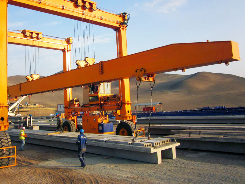
Spreader Beams (Standard Solution)
This is the most widely used and safest option for precast beams.
A spreader beam keeps lifting forces vertical, removing horizontal pressure on the concrete. This is critical for maintaining beam shape, especially for I-girders and T-beams.
Telescopic designs are commonly used in production lines to adapt to different beam lengths quickly.
Best used for:
- I-girders and T-beams
- Most standard precast lifting operations
- Projects requiring consistent quality and speed
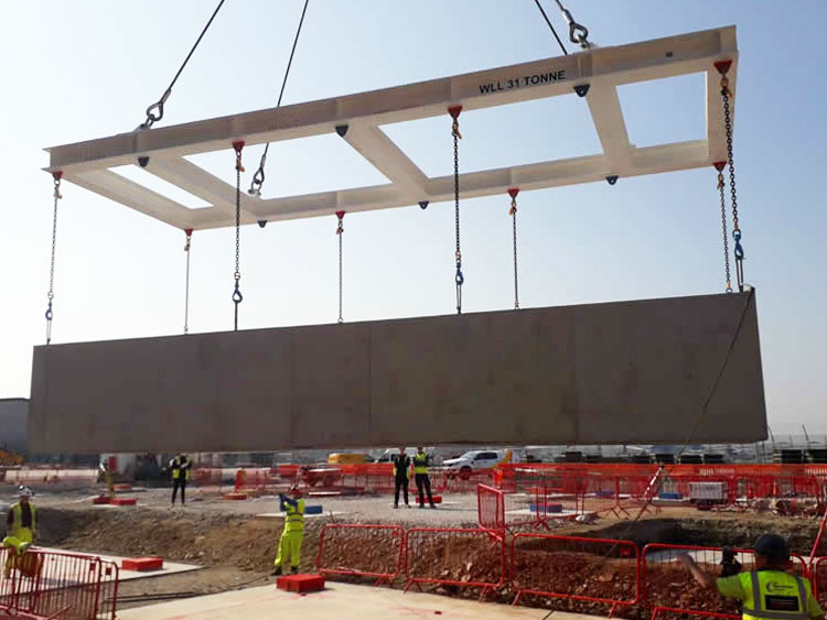
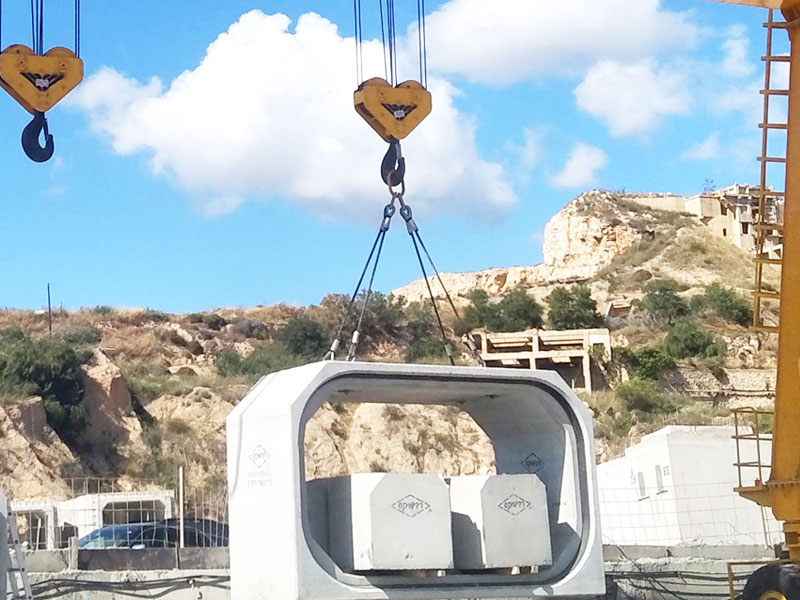
Lifting Frames (For Wide or Unstable Sections)
When beams are wide or structurally sensitive, a spreader beam alone is not enough.
Lifting frames support the beam from multiple points, forming a rigid structure that prevents twisting or deformation during lifting.
Without this, U-beams or box sections can easily distort – especially right after demolding.
Best used for:
- U-beams
- Wide slabs
- Box girders and segmental components
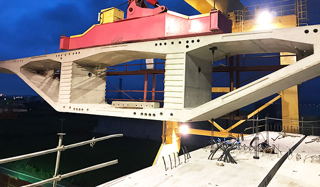
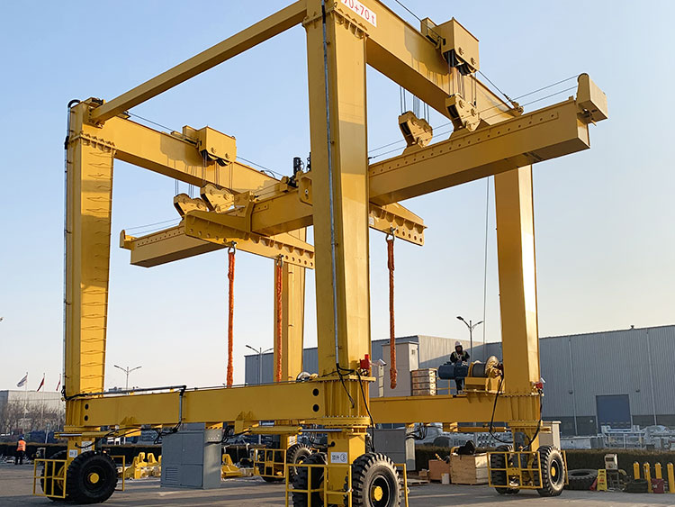
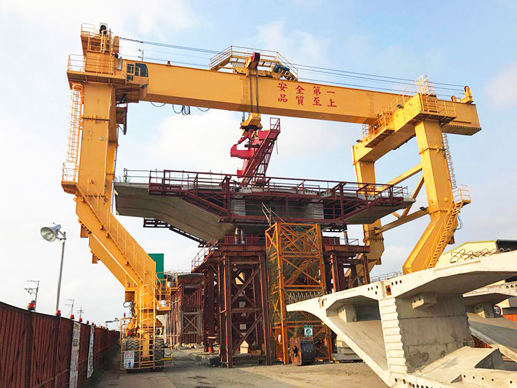
Integrated Lifting Systems (Heavy-Duty Projects)
For large-scale infrastructure, lifting is often built into the crane system itself.
These systems use synchronized hoists or rigid connections to control every lifting point precisely. This reduces human error and improves repeatability in high-cycle operations.
Best used for:
- Heavy precast elements (100t+)
- Repetitive lifting operations
- Projects where precision and safety are critical
There is no one-size-fits-all solution in precast lifting. Slings, spreader beams, lifting frames, and integrated systems are all available in a wide range of structural configurations and are typically customized to match specific beam geometry and cross-sectional requirements. In practice, variations in beam shape, size, and lifting point arrangement require different structural forms and load distribution strategies. A properly tailored lifting system ensures not only structural safety, but also smoother handling throughout production, storage, and installation.
Safety Enhancement Measures for Precast Concrete Lifting
After defining the rigging arrangement and selecting the appropriate lifting setup, additional safety measures are implemented to enhance operational stability and reduce handling risks. These measures do not replace the engineered lifting design, but rather reinforce its performance under real construction conditions.
Edge Protection for Concrete Elements
Concrete edges are highly vulnerable during lifting due to localized contact stresses from slings, clamps, or lifting devices. To prevent surface damage and stress concentration, protective measures are applied at all contact points, including:
- Synthetic slings with soft bearing surfaces
- Rubber pads or engineered corner protectors
- Controlled contact geometry between rigging and concrete surface
These measures help distribute contact pressure and reduce the risk of spalling or edge cracking.
Synchronized Lifting for Load Stability
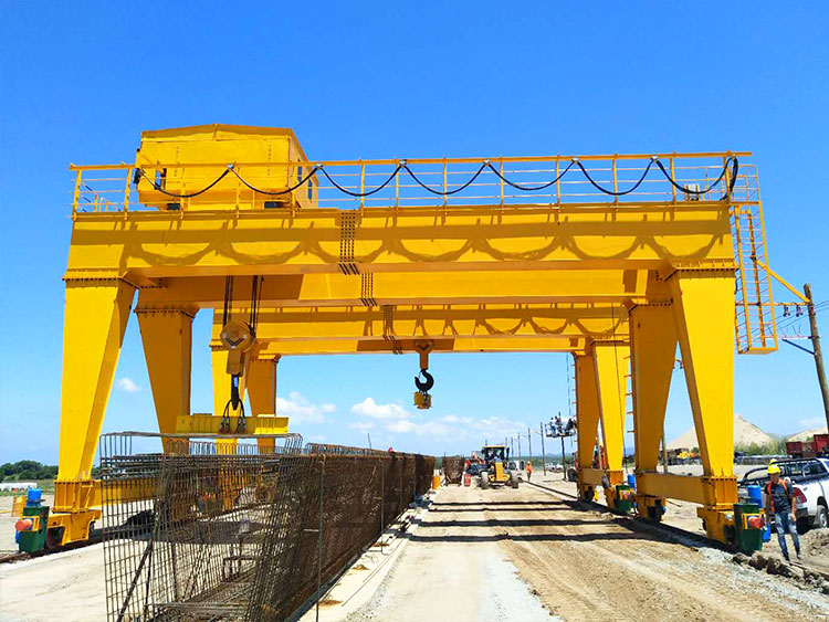
For long-span or heavy precast girders, synchronized lifting is essential to maintain load balance across multiple lifting points. This is particularly important when using:
- Tandem straddle cranes
- Multi-hook gantry systems
- Multi-point lifting frames
Synchronized hoisting ensures that all lifting points rise uniformly, preventing torsional stress and unintended rotation during elevation.
Control of Dynamic Effects
During lifting operations, crane movement, acceleration, and environmental conditions introduce dynamic forces that can exceed static load conditions. To manage these effects:
- Smooth start and stop operations are applied
- Load acceleration is controlled through crane systems
- Anti-sway technologies are used to minimize pendulum motion
These controls help maintain load stability during transport and positioning.
Center of Gravity Monitoring and Alignment
Even with a well-designed rigging system, slight deviations in center of gravity can affect stability during lifting. To mitigate this risk:
- Pre-lift COG estimation is verified before operation
- Adjustable rigging systems are used when necessary
- Load balance is checked during initial lifting phase
Proper alignment ensures that the precast element remains stable and does not tilt during hoisting.
Reinforcement of Lifting System Safety
In addition to operational controls, mechanical safety reinforcement may be applied depending on project complexity. This includes:
- Load monitoring systems for real-time force tracking
- Redundant lifting points for critical components
- Secondary safety attachments for high-risk lifts
These systems provide additional assurance in case of unexpected load variation or environmental influence.
Precast Handling Strategies Across Different Work Environments
In precast lifting operations, environmental conditions play a critical role in determining how lifting systems are executed in practice. While rigging strategies, lifting setups, and safety measures are designed based on engineering principles, their actual performance depends on the working environment.
In the Production Yard
The production yard is a controlled environment with fixed gantry cranes and repetitive lifting cycles.
- Stable ground and standardized operations
- Fixed or rail-mounted cranes
- Repetitive lifting of similar elements
Strategy: Standardized spreader beams and fixed rigging layouts are used to ensure efficiency and consistency.
Focus: Speed, repeatability, and damage prevention during demolding and early lifting.
In the Storage Yard
The storage yard is a semi-controlled environment with variable stacking and access conditions.
- Irregular ground and stacked elements
- Limited crane positioning flexibility
- Variable lifting conditions
Strategy: Adjustable spreader beams or equalizer systems are used together with RTG cranes to accommodate different beam lengths, stacking heights, and load conditions.
Focus: Stability during lifting and safe handling from stacked positions.
At the Construction Site
The construction site is the most complex environment due to external and spatial constraints.
- Wind exposure and uneven ground
- Restricted working space
- High positioning accuracy requirements
Strategy: Synchronized lifting systems and anti-sway control are often required for stability and precision.
Focus: Load stability, accurate placement, and environmental control.
Engineering Safety into Every Precast Lift
If you are navigating the complexities of high-capacity precast handling, Aicrane team is here to provide the engineering insights and specialized equipment configurations needed to secure your project’s success. Let’s discuss how to optimize your next lifting operation for maximum safety and structural protection.