

RTG crane safety systems ensure stable and reliable operation in demanding industrial environments such as container handling, steel yards, precast concrete plants, shipyards, and large manufacturing facilities, where heavy loads, continuous lifting, and complex yard traffic create constant operational pressure. Under these conditions, risks such as load sway, overload, uneven ground impact, and interference from simultaneous equipment movement require precise control and a multi-layer safety system to maintain stable performance during lifting, traveling, and stacking operations.
RTG Crane Safety System Overview
RTG crane safety depends on the coordinated operation of structural, mechanical, electrical, and monitoring systems. Together, these systems help maintain stable load handling, controlled movement, and reliable performance under varying operating conditions. The overview below highlights the key safety systems used in RTG cranes and the primary risks they are designed to address.
| Safety System | Key Functions | Risks Controlled |
|---|---|---|
| Structural Safety System | Frame strength, load distribution, stability control | Tipping, deformation, uneven ground effects |
| Motion Control Safety System | Anti-sway control, braking, travel correction | Load swing, collision, uncontrolled movement |
| Electrical Protection System | Power distribution, cable protection, emergency shutdown | Electrical failure, short circuit, power loss |
| Intelligent Monitoring System | Load monitoring, wind detection, obstacle sensing | Overloading, environmental risks, delayed response |
The following sections examine each system in greater detail, explaining how structural design, motion control, electrical protection, and intelligent monitoring contribute to safe and reliable load handling.
Structural Safety System: Load-Bearing and Stability Design for RTG Cranes
The structural safety system ensures stable performance of rubber tyred gantry cranes under full load, dynamic travel, and environmental conditions including temperature variation and uneven ground. Applicable to steel yards, precast plants, logistics terminals, and heavy equipment storage areas, it maintains operational stability through controlled structural rigidity, accurate load distribution, and regulated ground adaptability.
Structural Strength and Frame Rigidity
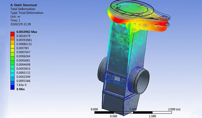
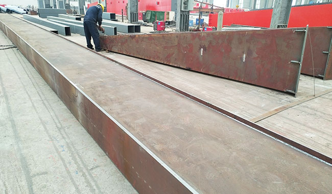
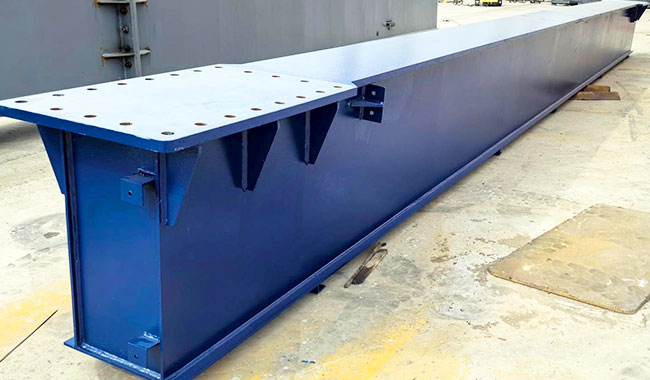
Box Girder Structural Design
The main girder adopts a welded box-type structure, verified through finite element analysis (FEA) to evaluate stress distribution and deformation under rated load, trolley movement, and dynamic operating conditions. This ensures structural reliability in continuous-duty industrial handling environments.
Material Selection by Operating Environment
High-strength steels are selected according to application and climate conditions. Q235B and Q355B are used for standard industrial sites such as inland workshops and logistics yards, while Q355E is applied in low-temperature regions to maintain impact toughness and long-term structural stability.
Structural Safety Margin Design
A safety factor of ≥1.5 is applied to ensure sufficient load-bearing capacity under rated lifting and dynamic operation, supporting safe performance in outdoor or semi-outdoor industrial environments with variable wind and duty cycles.
Load Distribution and Center of Gravity Control
Lower-Center-of-Gravity Layout
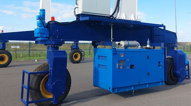
Heavy components such as diesel generator sets, hydraulic power units, and electrical control cabinets are installed in lower structural or under-beam positions to reduce vertical center of gravity and improve overall stability.
Structural Load Balance
The crane structure is designed with geometric symmetry, allowing dead weight to be evenly distributed across drive and idle wheel groups during travel, reducing localized wheel loading.
Ground Adaptability and Stability Protection
Wheel Configuration for Load Distribution
RTG cranes adopt different wheel group configurations based on lifting capacity and structural design requirements, typically including 4, 8, 16, or 32-wheel arrangements.
Wheel groups are arranged along the crane frame according to load transfer points, allowing the total load to be distributed through multiple bogie assemblies into the ground.
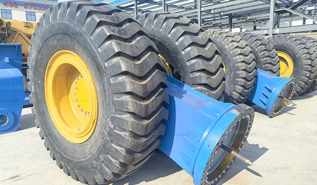
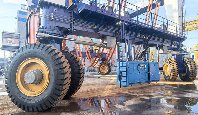
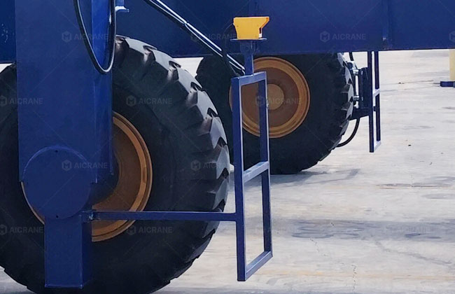
Engineering Bias-Ply Pneumatic Tire System
Industrial bias-ply pneumatic tires are used as the main ground contact medium for RTG crane applications.
These industrial tires are designed to provide high load-bearing capacity and structural durability, while offering controlled vertical flexibility under working loads. The tire-ground contact area adjusts under load conditions to maintain stable and continuous contact during crane travel on industrial surfaces.
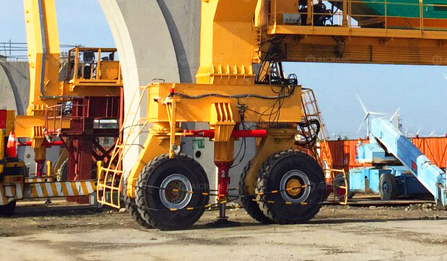
Hydraulic or Mechanical Suspension System
For heavy-duty RTG applications such as road and bridge construction, a hydraulic or mechanical suspension system may be applied to enhance load stability and ground conformity.
Mechanical suspension relies on articulated bogie movement for passive load sharing, while hydraulic suspension uses cylinder-based support to provide controlled vertical adjustment under uneven ground conditions.
Motion Control System: Precision Movement and Anti-Sway Performance for RTG Cranes
AICRANE RTG cranes use PLC-based control systems with encoder feedback to manage lifting, travel, and steering operations. The system continuously adjusts motion based on real operating conditions to maintain stable and controlled load handling.
Anti-Sway Control System
The anti-sway system reduces load swing by adjusting trolley speed based on feedback from the hoisting drum encoder.
The encoder provides real-time information on rope length, which affects how the load behaves during movement. The PLC uses this feedback to adjust the trolley acceleration and deceleration through the VFD, helping reduce load swing during start, stop, and positioning.
This control method improves load stability during normal lifting and transfer operations, especially when handling long or heavy loads.
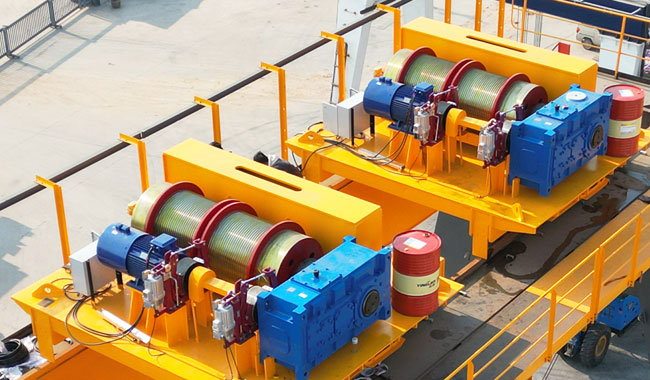
Dual Hoisting Brake System
The hoisting system is equipped with two independent braking devices to ensure safe load holding.
The motor brake is used during normal lifting and lowering operations. It works together with the VFD to control smooth deceleration and stopping.
The drum brake is a safety brake installed directly on the hoisting drum. It activates when abnormal conditions are detected, such as overspeed or a failure in the drive system. In this case, the brake holds the load directly at the drum, independent of the gearbox and motor.
Travel Synchronization and Deviation Correction Control
Each wheel group is driven by an independent motor system and monitored by speed encoders. The PLC continuously compares encoder feedback from the left and right drive systems during travel.
If a deviation is detected, the PLC adjusts the speed reference signals of the VFDs to maintain synchronized operation between both sides. This closed-loop control system helps minimize crane skewing and ensures stable straight-line travel performance, particularly on uneven ground or under varying load conditions.
Steering Mode Control and Safety Interlock
RTG cranes support multiple steering modes, including straight travel, crab steering, and pivot turning.
The system only allows steering mode changes when the crane is fully stopped or moving at very low speed.
Before switching modes, the system checks wheel position feedback to ensure all wheel groups have reached the required steering angle within an acceptable range. The new steering mode is activated only after confirmation.
This helps reduce tire stress and ensures safe steering transitions during operation.
Electrical Safety & Control System: Power Distribution and Operational Safety for RTGs
The electrical system is a core safety component of RTG cranes, directly affecting control accuracy, operational stability, and overall site safety. Through robust system design and the use of high-quality electrical components, the system minimizes failure risks and ensures long-term operational reliability in demanding environments.
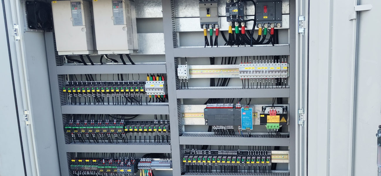
Electrical Control Cabin
The electrical control cabin integrates the PLC system, frequency inverters, and key protection devices, serving as the central hub of crane electrical control.
Under normal conditions, advanced PLC and VFD technology ensure precise motion control, smooth start/stop performance, and stable operation. The cabinet is built with an IP55 protection rating, providing effective resistance against dust and water ingress for reliable operation in industrial environments.
For low-temperature applications, the cabin is equipped with heating elements and a thermostat-controlled system. This maintains stable internal conditions, prevents condensation, and ensures consistent performance of electrical components under extreme weather conditions.
Main Electrical Components
Critical components such as contactors and relays are sourced from leading global brands including ABB, Siemens, and Schneider.
These components are selected for their high durability, stable performance, and strong electrical reliability, helping reduce maintenance requirements and improve overall system safety throughout the crane lifecycle.
Frequency Inverter System
The VFD system adopts premium brands such as ABB, Yaskawa, and Schneider to control hoisting and travel mechanisms.
It enables smooth acceleration and deceleration, reducing mechanical stress and improving operational safety. Multi-speed control capability allows flexible operation under different load conditions, enhancing both efficiency and control stability.
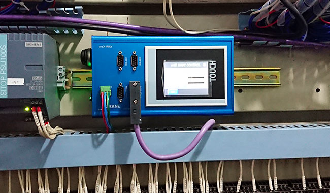
PLC Control System
The system is controlled by a Siemens PLC, which acts as the central logic and safety unit.
It manages coordinated crane movements and supports real-time monitoring of system status. Built-in diagnostic functions detect faults such as overload, phase loss, or communication errors and trigger protective responses, ensuring safe and reliable operation.
The system also supports industrial communication interfaces for integration and remote monitoring, improving operational transparency and maintenance efficiency.
Industrial Aviation Plugs
Electrical connections use DELIXI IP67-rated industrial aviation plugs.
These connectors provide high sealing performance, vibration resistance, and quick installation. They reduce wiring complexity and improve connection reliability, minimizing risks caused by loose or faulty connections.
Diesel Generator System (Diesel RTG)
For diesel-powered RTG systems, the power unit consists of a Cummins diesel engine paired with a Stamford generator, installed in a soundproof enclosure.
A SmartGen control system provides real-time monitoring of key parameters including voltage, frequency, and engine status. Built-in protection functions such as overspeed, low oil pressure, and high temperature ensure safe and stable power output for continuous crane operation.
Cable Reel System (Cable-powered RTG)
For cable-powered RTG cranes, a constant-tension cable reel system is used with guide rollers to manage cable movement during travel.
The system maintains stable cable tension through constant torque control, ensuring smooth winding and unwinding without twisting or overstress. High-strength, wear-resistant cables further enhance durability and operational safety under continuous heavy-duty use.
Intelligent Monitoring System: Equipment Condition Awareness for RTG Cranes
The intelligent monitoring system is designed to collect and transmit real-time operating data from key RTG crane subsystems. It focuses on equipment condition visibility, operational status tracking, and environmental awareness during continuous yard operations. This system does not control crane motion, but provides the data foundation for safe operation and maintenance decisions.
Load Condition Monitoring System
Load monitoring provides continuous visibility of lifting conditions during hoisting operations.
- Hoisting load is measured through load monitoring devices integrated into the lifting system
- Rope tension data is collected during lifting and lowering cycles
- Load values are transmitted to the control system for operator display and record
👉 This allows operators to observe lifting conditions during handling operations.
Motion & Position Monitoring System
Motion monitoring provides feedback on crane movement and positioning across hoisting and travel systems.
- Hoist position is monitored through lifting position feedback devices
- Travel distance and speed are recorded through gantry movement tracking systems
- Steering position data is collected during direction changes
- Movement data is displayed in the operator cabin interface
👉 This provides visibility of crane movement during yard operation.
Tire & Travel Condition Monitoring
As RTG cranes operate on rubber tires, wheel-ground conditions are continuously monitored.
- Tire pressure and temperature are monitored during operation
- Wheel load distribution data is collected across axle groups
- Travel deviation between left and right gantry sides is recorded
- Wheel slip conditions are detected by comparing movement and rotation data
👉 This provides operating data related to travel stability on yard surfaces.
Environmental Condition Monitoring System
Environmental monitoring provides operating condition data for outdoor yard environments.
- Wind speed is measured through upper structure monitoring devices
- Electrical cabinet temperature and humidity are recorded during operation
- Environmental data is displayed in the operator interface for reference
👉 This provides environmental awareness during outdoor operation.
Equipment Condition Monitoring System
Equipment monitoring tracks the operating condition of major mechanical and electrical components.
- Motor operating temperature is recorded during load cycles
- Drive current data is collected from frequency converter systems
- Brake condition data is monitored for wear status indication
- Engine operating parameters are recorded in diesel or hybrid systems
👉 This provides equipment condition visibility during continuous operation.
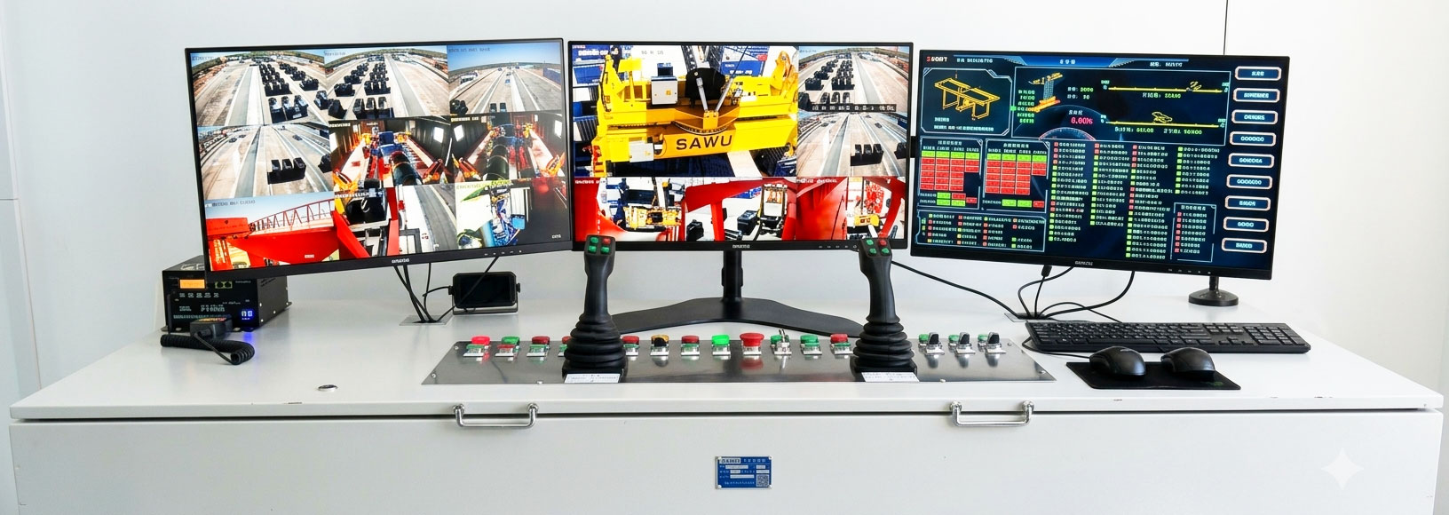
Data Acquisition & Operator Interface System
All monitoring data is collected and transmitted to the control interface through industrial communication systems.
- PLC-based data acquisition collects signals from monitoring devices
- Industrial communication networks transmit data between subsystems
- Operator cabin HMI displays operating status and system parameters
- Historical data is stored for maintenance reference
👉 This ensures centralized visibility of crane operating conditions.
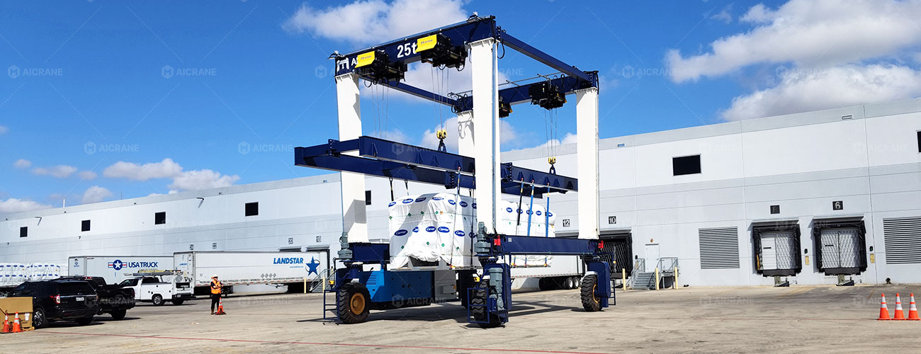
Application Case: Safe Handling of High-Value Precision Equipment in a Logistics Yard
Project Overview
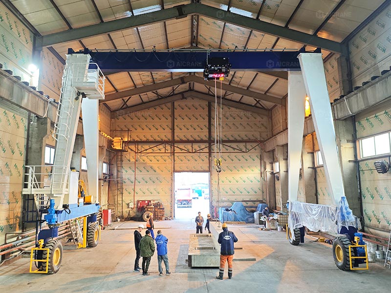
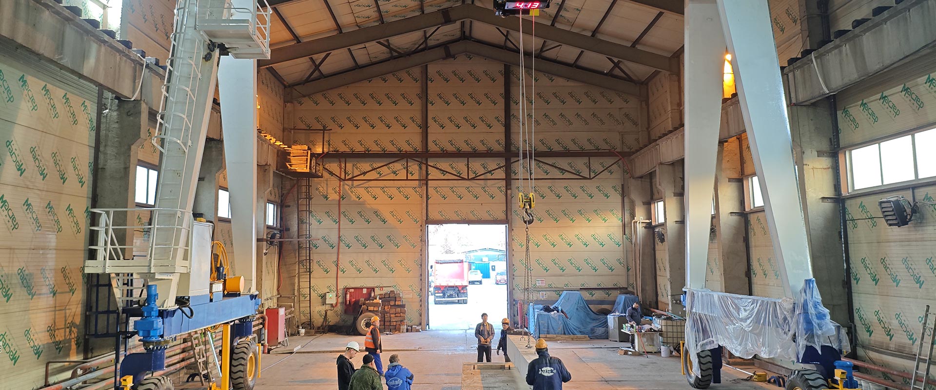
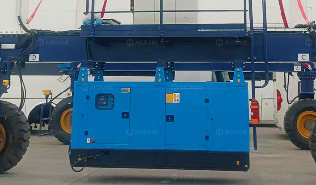
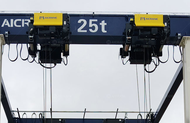
A 25-ton rubber-tyred gantry (RTG) crane is deployed in a logistics yard for handling high-value precision industrial equipment such as HVAC chillers and power modules.
The system features a 25-ton dual-hoist trolley and an Integrated Spreader System designed for flexible multi-point sling lifting, enabling safe handling of oversized and non-standard cargo in outdoor yard conditions with defined travel lanes and staging zones.
Key Operational Challenges
Precision equipment handling in RTG operations presents several critical risks:
- Shifted center of gravity due to uneven internal load distribution
- Surface damage caused by localized lifting stress
- Clearance limitations in narrow yard travel corridors
These conditions require precise coordination between lifting balance, travel stability, and spatial safety control.
Engineering & Safety Solutions
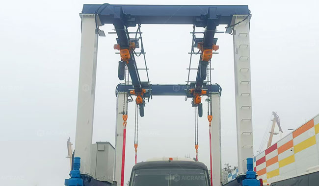
- Dual-Hoist VFD Synchronization System: Independent variable frequency drives (VFDs) synchronize both hoists with real-time encoder feedback, ensuring equal vertical displacement and preventing spreader tilt during lifting and lowering operations.
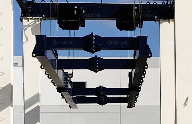
- Integrated Multi-Point Spreader System: The flexible sling-based spreader distributes lifting forces across multiple points, reducing localized stress and preventing deformation of sensitive equipment. Load feedback monitoring ensures balanced force distribution throughout the lift.
- Proximity-Based Anti-Collision System: Installed at the wheel-end and travel front zone, the system continuously monitors obstacles in real time. When a safety threshold is reached, it automatically reduces speed, triggers alarms, or stops motion to ensure safe navigation in constrained yard spaces.
Operational Results
- Stable multi-point lifting of high-value industrial equipment without structural deformation
- Maintained load balance throughout hoisting and transportation cycles
- Eliminated localized compression damage through distributed force lifting
- Improved operational efficiency between storage and loading zones
Integrated Safety Solution for Reliable RTG Crane Operations
The RTG crane safety system is an integrated engineering framework combining structural stability, motion control, electrical protection, and intelligent monitoring. These systems work together to ensure stable load handling, precise movement, and safe operation in demanding outdoor yard environments.
As safety and efficiency requirements continue to increase in modern logistics operations, advanced RTG safety design plays a key role in maintaining reliable and productive crane performance.
For customized RTG crane safety solutions, please contact AICRANE engineering team for technical support and project consultation.