


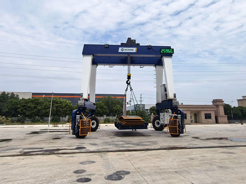
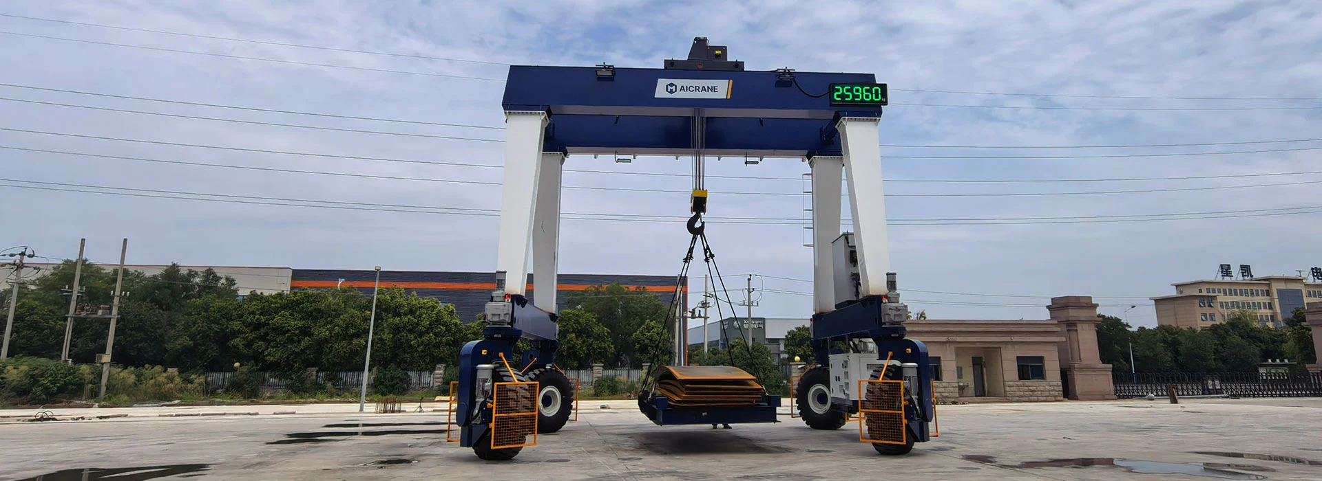
Aicrane provides highly customized RTG rubber tyred gantry crane solutions designed for complex industrial handling requirements. Through flexible configuration of lifting systems, crane structures, mobility systems, power supply, and control technologies, each crane is engineered to match specific load characteristics and operational needs.
Customized Hoisting System Configuration
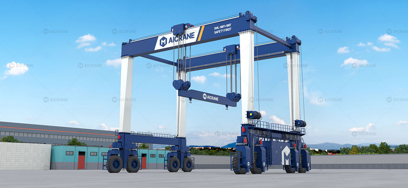
The hoisting system is a critical component of a rubber tyred gantry crane, directly influencing lifting capacity, load stability, and positioning accuracy. Aicrane provides customized hoisting solutions by determining lifting capacity, selecting suitable hoisting mechanisms, configuring multiple hoisting units, and designing load-specific lifting attachments according to load characteristics, operating requirements, and handling conditions.
Hoisting Performance Configuration
Lifting Capacity and Duty Class Configuration
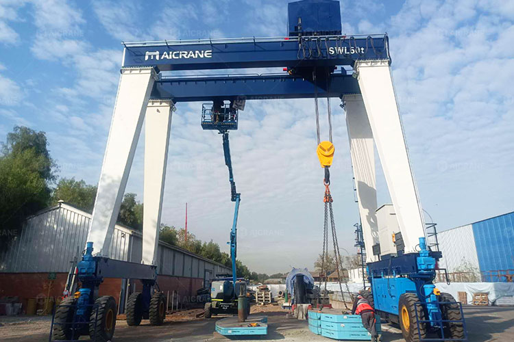
Aicrane configures hoisting systems from 5t to 800t+ based on actual load requirements. Duty class selection considers lifting cycles, operating hours, and service conditions to ensure reliable performance for applications ranging from intermittent material handling to continuous heavy-duty operation. Hoisting speed and motor capacity are matched with load characteristics and operating frequency to achieve efficient and stable lifting performance.
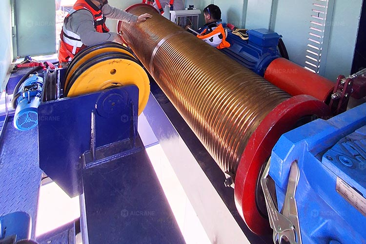
Transmission, Braking & Load Control Configuration
Transmission and braking components are selected according to lifting torque, operating frequency, and load impact. Heavy-duty configurations can incorporate reinforced gear reducers, upgraded couplings, and dual braking systems to provide stable load holding, smooth stopping, and reliable performance during frequent lifting cycles.
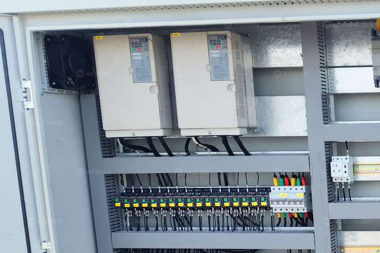
VFD-Based Precision Lifting Control
Variable Frequency Drive (VFD) systems are configured according to required lifting accuracy and handling conditions. They provide smooth acceleration, deceleration, and low-speed inching control, helping reduce mechanical impact and improve load positioning accuracy during lifting and placement operations.
Hoisting Unit Configuration
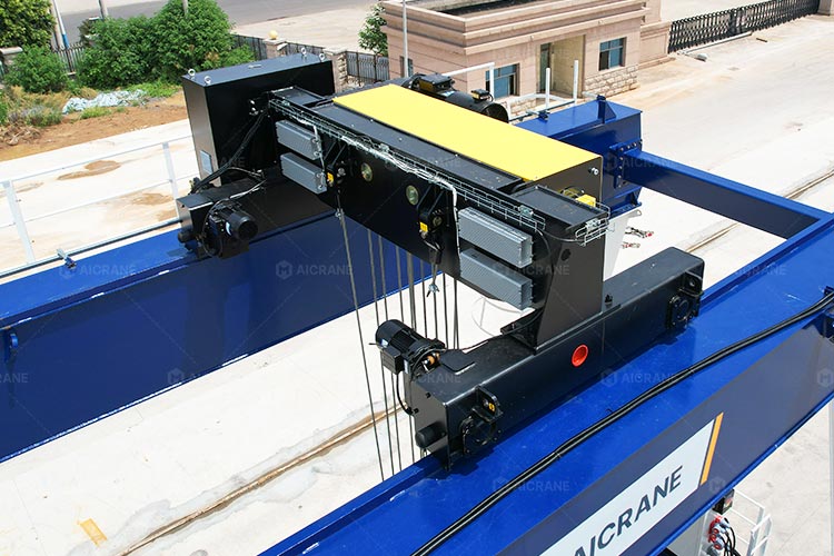
European Type Wire Rope Hoist
Designed for applications requiring smooth operation and precise load positioning. Its compact trolley design makes better use of the available lifting height, while integrated VFD control ensures smooth lifting and accurate load placement.
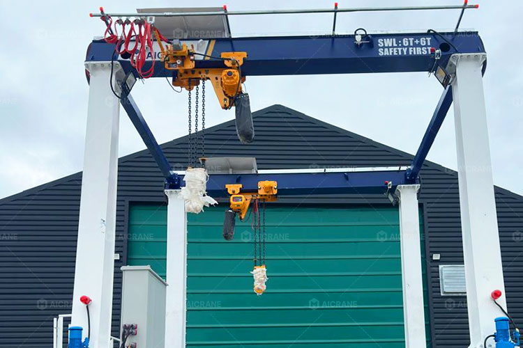
Electric Chain Hoist Configuration
Designed for light to medium-duty lifting where installation space or headroom is limited. The compact hoisting unit reduces the installation footprint, and the high-strength alloy load chain provides reliable lifting performance with simple maintenance.
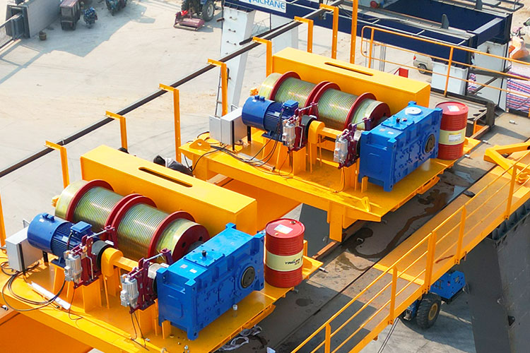
Winch-Based Hoisting Configuration
Designed for high-capacity lifting applications that require greater lifting force or extended lifting heights. The winch drum, wire rope, sheave arrangement, and trolley configuration are selected according to the load and lifting requirements, ensuring stable performance under heavy-duty conditions.
Multi-Hoist Synchronized Lifting Design
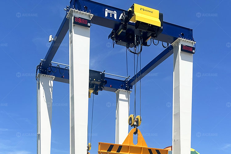
Dual-Hoist Synchronized System
Two independent hoists operate under synchronized control to maintain balanced lifting. This configuration is suitable for long pipes, steel beams, fabricated structures, and other loads requiring two-point support.
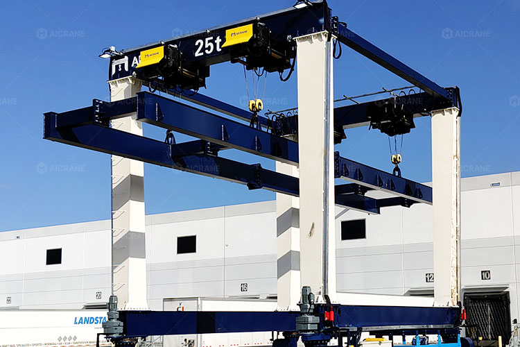
Four-Point Lifting Configuration
Four synchronized hoists provide distributed lifting support for large or deformation-sensitive components. The configuration helps reduce concentrated stress and improve stability when handling wind turbine components, precast panels, and modular structures.
Specialized Lifting Attachment Design
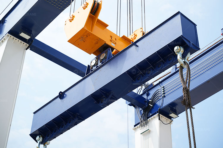
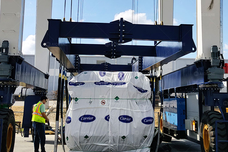
Spreader Beams
Designed with adjustable lifting centers and optional rotation functions to improve load alignment and stability when handling long precast concrete elements, steel structures, and oversized components.
Custom Lifting Frames
Tailored for irregularly shaped machinery modules and industrial equipment, with fixed or adjustable suspension points designed according to the load center of gravity.
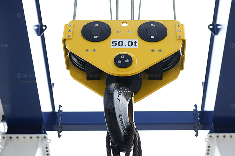
Specialized Hooks & Interfaces
Customized hooks, swivel devices, C-hooks, and quick-connection systems can be developed for different material handling requirements, improving rigging efficiency and operational safety.
Customized RTG Steel Structure Design
The steel structure of an RTG crane directly determines load-bearing capacity, structural rigidity, working coverage, and operational stability. Aicrane customizes main girders, portal frames, and structural dimensions according to lifting requirements, load characteristics, site layout, and traveling conditions to achieve the required strength, stability, and handling flexibility.
Customized Girder Structure
The main girder configuration and dimensions are customized according to lifting capacity, span length, working duty, load distribution, and structural performance requirements.
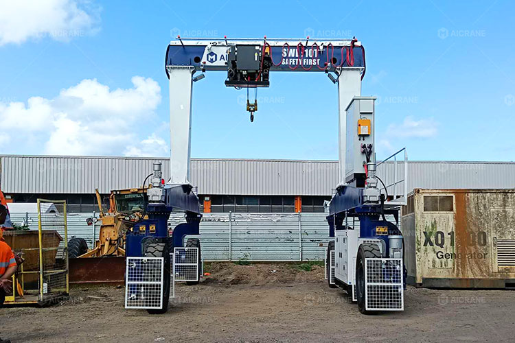
Single Girder RTG Structure
A lightweight box girder design is applied for applications requiring reduced structural weight and efficient material handling performance.
- Reduced deadweight and wheel loads
- Compact structural layout with efficient space utilization
- Lower investment and maintenance requirements for light and medium-duty operations
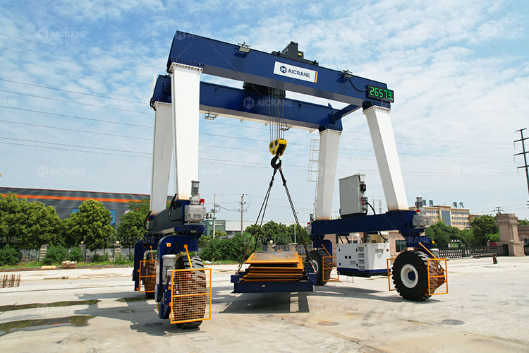
Double Girder RTG Structure
A reinforced double girder design is configured for higher lifting capacity, larger spans, and increased structural rigidity requirements.
- Higher torsional stiffness and load-bearing capability
- Reinforced girder sections and structural connections for heavy loads and frequent-duty operations
- Improved resistance to deformation under repeated lifting and traveling cycles
- Suitable for multi-hoist arrangements and large structural loads
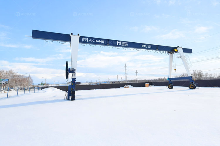
Double-Side Cantilever Overhang Design
An extended girder design is configured for applications requiring increased working coverage beyond the main portal area.
- Extended trolley travel range on both sides of the main girder
- Expanded handling coverage without increasing overall wheel track width
- Reinforced cantilever structure to maintain rigidity and stability under extended loading conditions
Portal Frame Structural Design
The portal frame structure and dimensions are customized based on site conditions, lifting height, material dimensions, and transportation requirements to ensure sufficient working space and stable operation. Customization options include:
Customized Span, Height, and Under-Beam Clearance
Leg height, girder span, and vertical clearance are designed according to load dimensions, vehicle access requirements, and surrounding equipment layout.
Customized Portal Frame Configurations
A-frame, U-frame, and T-frame structures can be developed according to structural stability, side clearance, and working space requirements.
Optimized Structural Dimensions for Traveling Stability
Wheelbase, leg spacing, and frame geometry are engineered to maintain balanced load distribution and reduce structural stress during traveling, acceleration, and braking operations.
Customized Travel and Steering System for Flexible RTG Operation
The travel and steering system directly determines the mobility, maneuverability, and handling flexibility of an RTG crane. Aicrane customizes wheel arrangements, drive configurations, and steering systems according to load capacity, travel routes, operating space, and positioning requirements to achieve stable and efficient material transfer.
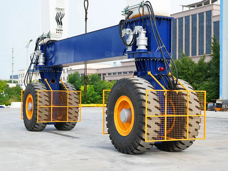
Wheel Arrangement and Independent Drive Configuration
The wheel arrangement and drive configuration are customized according to crane capacity, ground pressure requirements, and traveling stability requirements.
- 4-Wheel Configuration: Designed for light and medium-duty RTG applications, providing a compact layout, flexible maneuverability, and simplified maintenance.
- 8-Wheel Configuration: Each leg can be equipped with two wheels in longitudinal (front-and-rear) or transverse (side-by-side) arrangements to distribute wheel loads and improve traveling stability for higher-capacity handling operations.
- 16-Wheel and 32-Wheel Configurations: Applied for ultra-heavy RTG applications to distribute overall loads, reduce ground pressure, and enhance stability during heavy-load transportation.
- Independent Drive and Steering Units: Configured for synchronized wheel movement, smooth acceleration, and accurate positioning during travel operations.
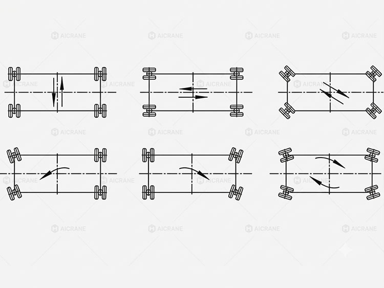
Steering Modes for Different Site and Mobility Requirements
Different steering modes can be integrated according to travel routes, available operating space, and maneuvering requirements.
- Straight-Line Travel: Provides efficient movement for long-distance transfer and fixed travel routes.
- 90° Steering: Enables lateral movement and direction changes where cross-transfer operations are required.
- Crab Steering: Allows diagonal movement for precise positioning and alignment in restricted or complex layouts.
- 360° Pivot Steering: Enables rotation within limited turning areas where maximum maneuverability is required.
Travel Drive System Configuration
The travel drive system can be configured according to different operating environment, mobility requirements, and available power conditions.
- Electric Travel Drive System: Equipped with VFD-controlled motors to provide smooth acceleration, precise speed regulation, and efficient operation for facilities with stable electrical power supply.
- Hydraulic Travel Drive System: Uses hydraulic wheel motors to provide high starting torque and stable low-speed operation. Combined with suitable suspension configurations, it improves traveling adaptability for uneven outdoor yards and applications requiring enhanced ground stability.
Travel Control and Synchronization System
Advanced travel control functions can be configured to improve movement accuracy, reduce mechanical stress, and maintain stable operation during long-distance travel and frequent handling cycles.
- Electronic Anti-Skew Control: Closed-loop PLC monitoring continuously compares travel speeds between left and right wheel groups and automatically adjusts speed differences to prevent frame skewing, uneven tire wear, and excessive mechanical stress.
- Synchronized Steering Control: Electronic control coordinates multi-wheel steering movements to maintain consistent wheel angles, enable smooth steering mode transitions, and improve positioning accuracy during complex maneuvers.
The following video shows the on-site testing of different RTG steering modes, demonstrating the flexibility, accuracy, and maneuverability of the customized travel and steering system under actual operating conditions.
Customized Power Supply Configuration for Different Operating Conditions
The power supply system is configured around job site infrastructure, required machine mobility, operating routes, and environmental standards. Aicrane provides different power configurations to match fully mobile outdoor operations, fixed-route industrial handling, and low-emission electric applications.
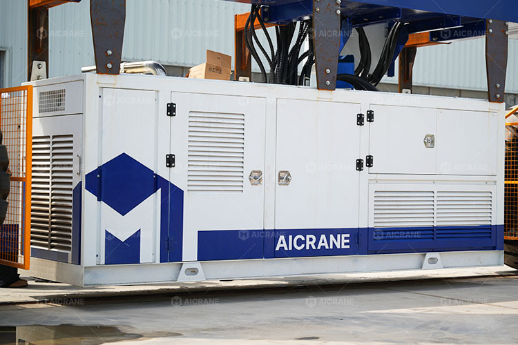
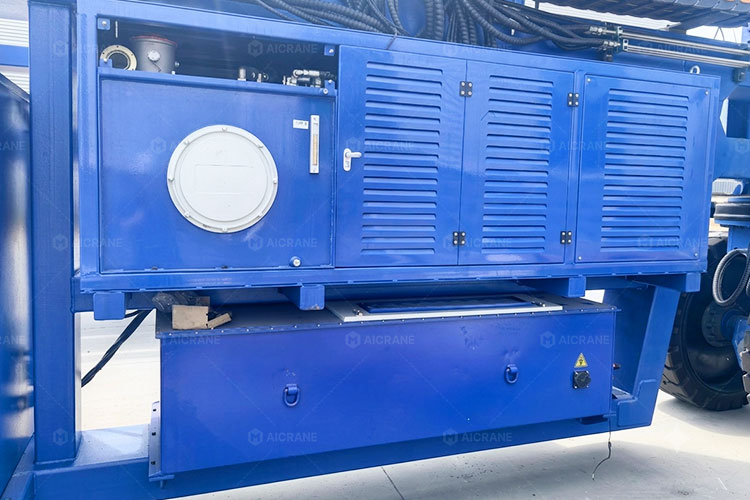
Diesel Generator Power Supply
For remote sites or large industrial yards without fixed electrical infrastructure, onboard diesel generator sets provide independent power for crane operation.
- Engine-Generator Matching: Generator capacity is configured according to peak power demands from hoisting, travel, steering, and auxiliary systems to ensure stable operation under different working cycles.
- Independent Operation Capability: Eliminates reliance on external cables or fixed power connections, allowing flexible movement between working areas and operation in locations without grid access.
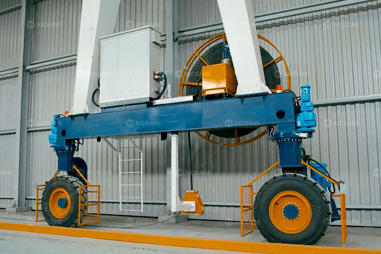
Cable Reel Power Supply
For operations with defined travel paths and available electrical infrastructure, cable reel systems provide continuous and reliable power supply.
- Customized Cable Management: Cable reel capacity, cable length, and tension control are configured according to travel distance, site layout, and power connection locations.
- Reduced Operating Cost: Direct electrical power supply reduces fuel consumption and maintenance requirements, making it suitable for frequent and continuous handling operations.
Battery Power Supply
For indoor facilities, noise-sensitive areas, and projects requiring cleaner operation, battery-powered systems provide flexible electric mobility.
- Optimized Battery Capacity: Battery capacity is configured according to operating hours, travel distance, lifting cycles, and charging requirements.
- Low-Noise Operation: Provides quiet and clean operation for indoor workshops, semi-enclosed facilities, and environmentally sensitive areas.
Customized Control System for Precise and Safe Handling
The control system is customized according to handling precision, automation requirements, operator preferences, and site safety conditions. Aicrane integrates motion coordination, operator interfaces, and safety monitoring functions to ensure smooth and coordinated operation of hoisting, travel, and steering systems.
Motion Coordination and Operator Interface Configuration
Control functions are configured according to crane operation methods, handling complexity, and required control accuracy:
PLC-Based Centralized Control
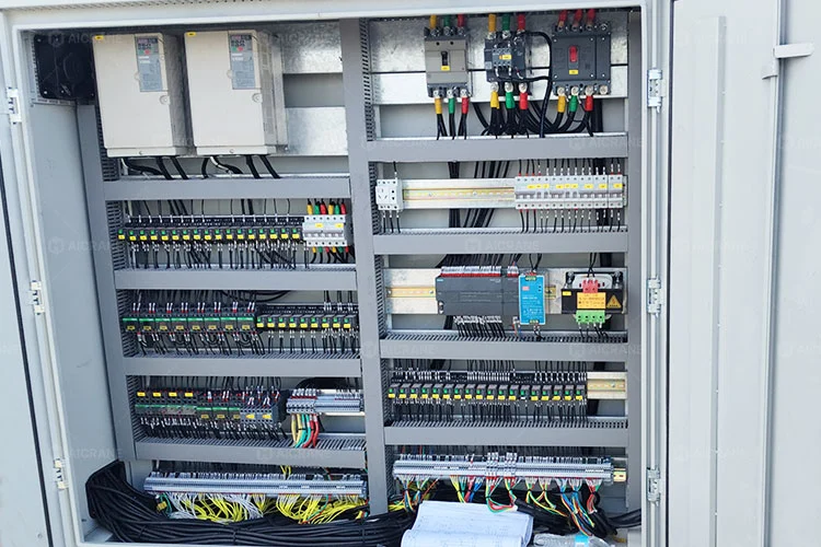
Coordinates hoisting, travel, and steering movements through integrated logic control, enabling smooth interlocks and precise multi-motion coordination during complex handling operations.
VFD Motion and Anti-Sway Control
Variable Frequency Drives (VFD) provide stepless speed regulation for hoisting and travel mechanisms. Soft-start and soft-stop functions reduce mechanical shock, while anti-sway control solutions can be integrated for improved load positioning during precise handling operations.
Multiple Operator Interface Options
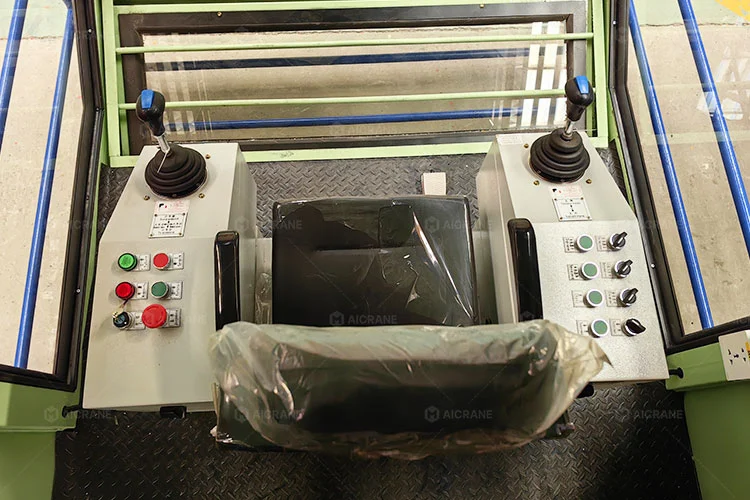
- Operator Cabin Control: Ergonomic cabin with optimized visibility for comfortable and precise operation during long working shifts.
- Wireless Remote Control: Provides flexible crane operation with improved visibility of the handling area, making load positioning more convenient.
- Wired Backup Control: A wired pendant controller is available as an emergency backup to ensure continued operation if wireless control is unavailable.
Customized Safety Monitoring and Protection Functions
Safety functions are configured according to operating risks, traffic conditions, and surrounding equipment layout to achieve safe and reliable load handling.
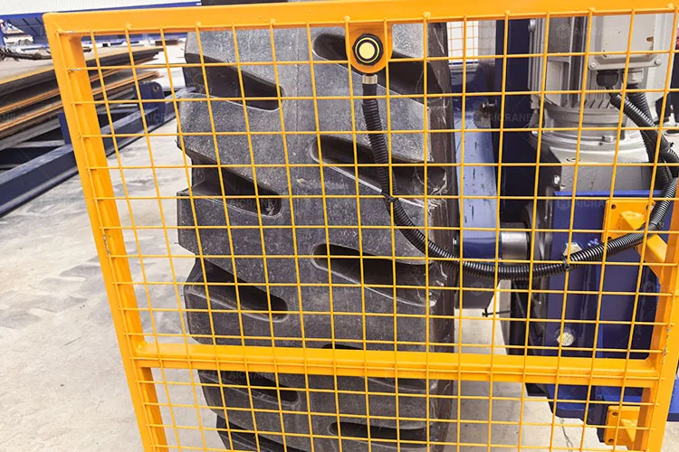
Ultrasonic Obstacle Detection and Blind-Area Monitoring
Compact ultrasonic sensors installed around travel and steering areas provide real-time distance monitoring of nearby obstacles, personnel, and vehicles, helping reduce blind areas during RTG operation.
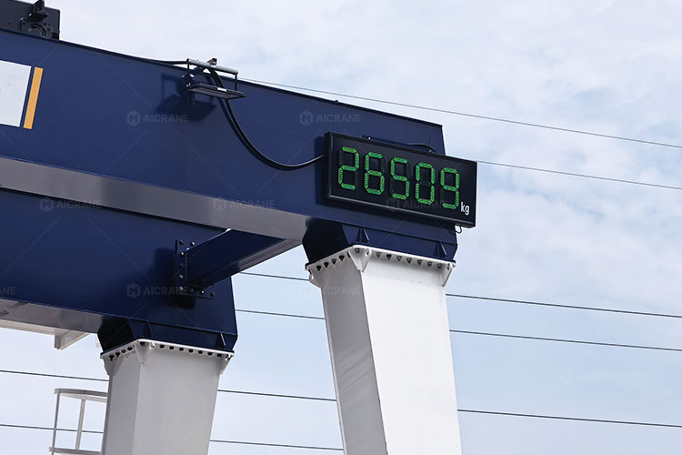
Real-Time Load Monitoring and Overload Protection
Load-cell-based monitoring continuously detects lifting load conditions and provides protection against overload operation and abnormal lifting situations.
Travel Limits and Zone Protection
Electronic travel limits and configurable protection zones restrict crane movement within predefined working areas and help prevent interference with surrounding equipment.
Operational Monitoring and Fault Diagnosis
HMI-based monitoring records operating parameters, fault information, and maintenance alerts to support troubleshooting and improve equipment availability.
Customized RTG Crane Projects Based on Specific Handling Needs
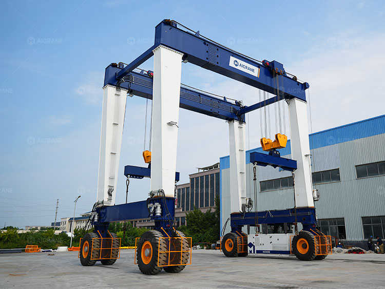
120T RTG Crane for Large Gas Tank Handling in the Middle East
Handling Requirement:
A Middle East customer required an outdoor lifting solution for transporting large gas tanks. Due to the tanks’ large dimensions and long structure, maintaining lifting balance and minimizing load sway during movement were critical challenges.
Customized Solution:
- Dual-hook lifting configuration with two parallel spreader beams to distribute the load and provide stable support for oversized gas tanks
- Synchronized mechanical and electrical control systems to maintain coordinated movement between the multiple lifting points and reduce uneven loading during operation
- Hydraulic drive system and reinforced double girder structure designed for stable outdoor transportation of heavy and oversized components
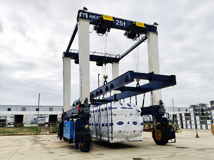
Customized 25T RTG Crane for HVAC Equipment Handling in USA
Handling Requirement:
A U.S. HVAC manufacturer required a compact outdoor lifting solution for handling large HVAC units in a limited storage yard. The crane needed stable lifting performance and customized load support to prevent deformation during handling.
Customized Solution:
- Compact structure with optimized 5.5 m span and 7.1 m lifting height for limited yard space
- Four electric hoists and adjustable lifting beam system for balanced lifting of large HVAC units
- Reinforced double girder design to improve load distribution and handling stability
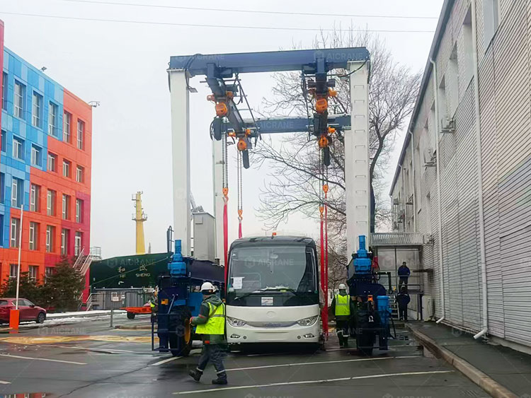
20T RTG Crane Designed for Bus Body Handling in Russia
Handling Requirement:
The customer required a 20-ton double girder RTG crane for handling bus bodies with the same width but different lengths. The lifting arrangement needed to adapt to varying body dimensions while maintaining balanced support during transportation.
Customized Solution:
- A secondary beam structure installed below the main girder allows the lifting points to be adjusted along the longitudinal direction to accommodate different bus body lengths.
- Flexible lifting point adjustment to match different bus body lengths and maintain proper load distribution
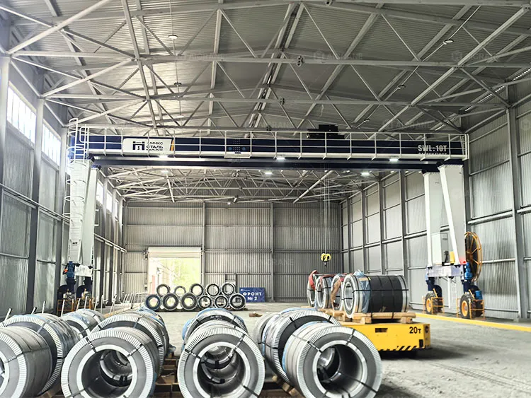
10T RTG Crane for Steel Coil Transfer Operations in Russia
Handling Requirement:
A steel products manufacturer in Russia was constructing a new workshop for steel coil storage operations. The crane design needed to maximize the available indoor space, achieve a wide working span, and operate reliably in a cold climate environment.
Customized Solution:
- 18 m span configuration designed to maximize workshop coverage and allow the crane to operate close to the building wall, making full use of available floor space
- Cable reel power supply selected for stable operation in low-temperature winter conditions, avoiding concerns related to battery performance in cold environments
Customized RTG Crane Design Process
Customization starts with understanding the actual handling requirements rather than applying a standard rubber tyred gantry crane configuration. Aicrane engineers evaluate load characteristics, operating conditions, and site requirements to develop a suitable RTG crane solution.
Load and Operation Requirement Analysis
The design process begins with evaluating the factors that directly influence crane performance:
- Load type, dimensions, weight distribution, lifting method, and handling frequency
- Required lifting capacity, positioning accuracy, and working duty
- Available operating space, travel routes, ground conditions, and environmental requirements
Customized System Configuration
Based on the application requirements, different components of the tyre gantry crane are configured to achieve the required performance:
- Hoisting capacity, lifting mechanisms, and attachments are selected according to load characteristics and handling requirements
- Girder structure, span, height, and clearance dimensions are designed to match site layout and working coverage
- Wheel arrangement, steering modes, and travel drive systems are configured according to mobility and maneuvering requirements
- Power supply and control functions are adapted to operating environment, energy requirements, and automation levels
Engineering Optimization for Reliable Operation
The final rubber tyred gantry crane design is optimized by coordinating structural, mechanical, electrical, and control systems to ensure:
- Stable lifting and traveling performance under actual working conditions
- Balanced load distribution and reduced mechanical stress during operation
- Reliable long-term performance under continuous industrial handling conditions
Every material handling application has different requirements. Share your load specifications, working environment, and operational expectations with Aicrane engineers to develop a customized rubber tyred gantry crane solution for your project.